
A kind of spinning equipment

A technology of spinning equipment and spinning wheel, which is applied in the field of metal pipe pressure processing, can solve the problems of low mold head, difficult demoulding of ultra-long thin-walled cylindrical parts, torsional deformation of workpieces, etc., and achieves the effect of small processing volume.

Active Publication Date: 2017-03-08
海鹰空天材料研究院(苏州)有限责任公司
View PDF11 Cites 0 Cited by
  • Summary
  • Abstract
  • Description
  • Claims
  • Application Information

AI Technical Summary

Problems solved by technology

[0005] The purpose of the present invention is to overcome the deficiencies of the prior art and provide a method that can solve the problems of difficulty in demoulding super-long thin-walled cylindrical parts, lowering of the mold, torsional deformation of the workpiece, bending deformation, material bulge at the rotary wheel, etc., and the tension direction can be adjusted. , Spinning equipment with smooth longitudinal movement of pipe fittings in the spinning process, and uniform wall thickness of ultra-long thin-walled cylindrical parts

Method used


Image

  • A kind of spinning equipment
  • A kind of spinning equipment
  • A kind of spinning equipment

Examples


Embodiment Construction

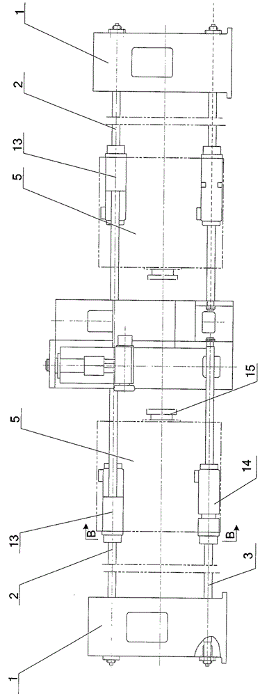
[0027] The invention as figure 1 As shown, it includes a bed 11, a rotary wheel mechanism, a support device 7, a longitudinal feed mechanism and a fixed short mandrel 12. The rotary wheel mechanism includes a rotary wheel 9 and a rotary wheel lateral feed mechanism 10, and the rotary wheel 9 passes through the rotary wheel. The feed mechanism 10 is fixed on the bed 11, the longitudinal position is fixed, the fixed short mandrel 12 penetrates into the spinning blank 8, and is longitudinally fixed at the position of the rotary wheel 9 through the mandrel tie rod 4, and the short mandrel 12 and the rotary wheel 9 are fixed The longitudinal position does not change during the spinning process.

[0028] The bed 11 is arranged and connected with various mechanical components and guide rails to withstand various forces and realize functions. The headstock and other components move on the guide rails. On the other hand, the bed is connected to the foundation through anchor screws to i...


PUM

PropertyMeasurementUnit
diameteraaaaaaaaaa

Abstract

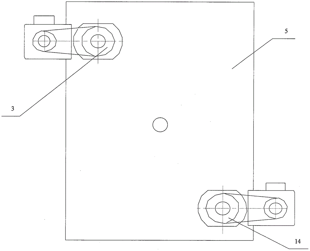
The invention provides a spinning device which comprises a lathe bed, a spinning roller mechanism, longitudinal feeding mechanisms and a fixing short core mold. A spinning roller is fixed to the lathe body through a transverse spinning roller feeding mechanism, and the longitudinal position of the spinning roller is fixed. The fixing short core mold penetrates into a spinning blank and is longitudinally fixed to the position of the spinning roller through a core mold pull rod. The longitudinal position of the fixing short core mold and the longitudinal position of the spinning wheel are not changed in the spinning process. The two sets of longitudinal feeding mechanisms are of the same structure and are installed at the two ends of the spinning roller mechanism respectively. The longitudinal feeding mechanisms comprise upper screw rods, upper nuts, lower screw rods, lower nuts, main shaft boxes, main shafts and connectors. The upper nuts and the lower nuts are fixedly connected with the main shaft boxes, and the nuts drive the main shaft boxes to move longitudinally along the screw rods. The connectors are installed at the ends of the main shafts, and the other ends of the connectors are connected with one end of the spinning blank. When the main shaft of the drive longitudinal feeding mechanism and the main shaft of the driven longitudinal feeding mechanism rotate synchronously, the two ends of the spinning blank rotate synchronously through the connectors. The spinning device integrates multiple functions, the technical problem in the forming process of super-long thin-wall cylinders is solved, low-cost, efficient and digital production of super-long cylinders and ultra-thin cylindrical parts is achieved, and high-reliability and high-quality production is achieved.

Description

technical field [0001] The invention relates to spinning equipment, which belongs to the technical field of pressure processing of metal pipes. Background technique [0002] Three-wheel powerful external spinning is currently the most important forming method for thin-walled cylindrical parts. It has the characteristics of large spinning tonnage, automatic centering of three-wheels, and high spinning precision. It is widely used in thin-walled cylindrical parts, Spin forming of parts with outer circumferential ribs and small taper angles. Due to the characteristics of the structure and function of the wheel mechanism, when spinning super-long (more than 10 meters in length) thin-walled (less than 10 mm in wall thickness) cylindrical parts, the mandrel must have sufficient strength, stiffness and surface quality. It is difficult to manufacture the mandrel. During the spinning process, it is difficult to demould the ultra-long and thin-walled cylindrical parts, and the mold i...

Claims


Application Information

Patent Timeline
Patent Type & Authority Patents(China)
IPC IPC(8): B21D22/16
CPCB21D22/16
Inventor 马世成王东坡吾志岗张晨
Owner 海鹰空天材料研究院(苏州)有限责任公司
Learn More