
Circular-blow cooling device

A cooling device and ring blowing technology, applied in the field of spinning manufacturing, can solve problems such as unfavorable melt spinning production and reduce production efficiency, and achieve the effects of easy cleaning and maintenance, high work efficiency and simple structure

Inactive Publication Date: 2019-10-22
JIANGSU UNIV OF SCI & TECH IND TECH RES INST OF ZHANGJIAGANG
View PDF9 Cites 3 Cited by
  • Summary
  • Abstract
  • Description
  • Claims
  • Application Information

AI Technical Summary

Problems solved by technology

[0003] However, because the production environment temperature of melt spinning is often high, so that the temperature of the cooling air blown in from the outside is generally high, which not only is not conducive to the production of melt spinning, but also reduces the production efficiency, and the produced spinning The various properties of the yarn are the same, which cannot meet the needs of various customers, because the elasticity and toughness of the fiber yarn have a certain relationship with the cooling temperature, so if you want to produce spinning with different properties, you must replace the ring air cooling device

Method used


Image

  • Circular-blow cooling device
  • Circular-blow cooling device
  • Circular-blow cooling device

Examples


Embodiment Construction

[0019] The specific implementation manner of the present invention will be described in more detail below with reference to schematic diagrams. The advantages and features of the present invention will be more apparent from the following description. It should be noted that all the drawings are in a very simplified form and use imprecise scales, and are only used to facilitate and clearly assist the purpose of illustrating the embodiments of the present invention.

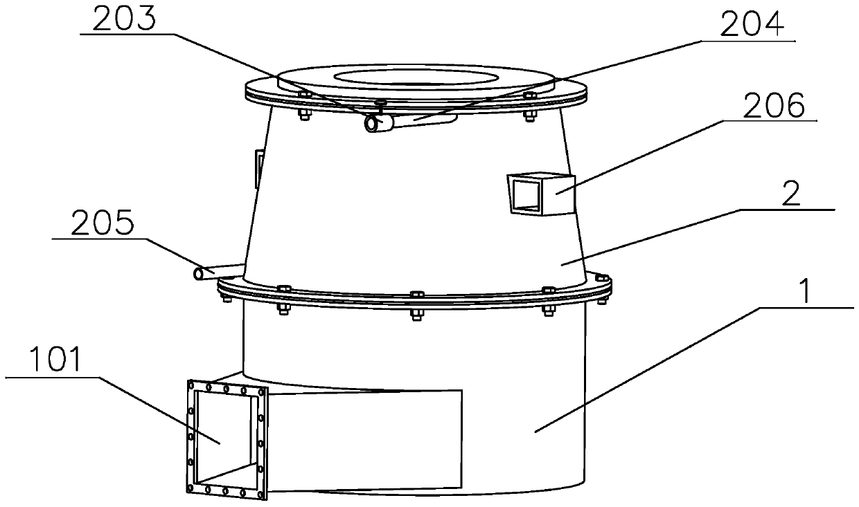
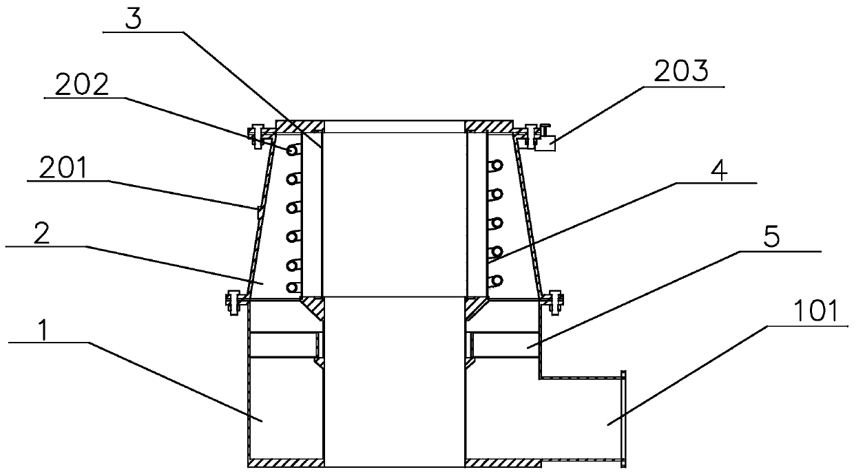
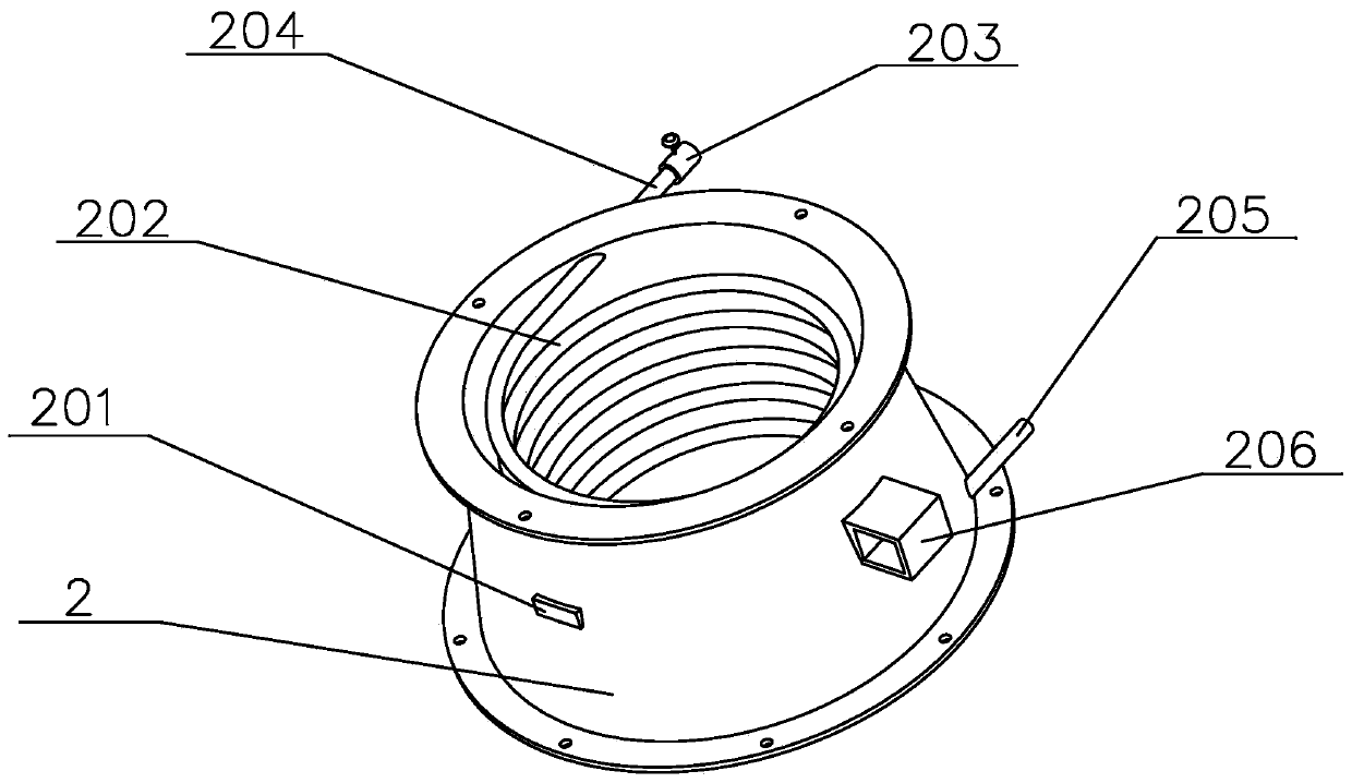
[0020] Such as Figure 1-Figure 3 As shown, the present embodiment provides a cooling device for surrounding air, including a lower air chamber 1, an upper air chamber 2, and an intermediate rectifying layer 5 between the lower air chamber 1 and the upper air chamber 2. The lower air chamber 1, the upper air chamber 2 Both the upper wind chamber 2 and the intermediate rectifying layer 5 are in a coaxial annular shape, the inner ring of the upper wind chamber 2 is a perforated plate 4, and the upper wind chamber 2 ...


PUM


Abstract

The invention provides a circular-blow cooling device, which comprises a lower air chamber, an upper air chamber and a middle rectification layer. The middle rectification layer is positioned betweenthe lower air chamber and the upper air chamber, and the lower air chamber, the upper air chamber and the middle rectification layer are circular coaxially. The inner periphery of the upper air chamber is provided with a porous plate, and the upper air chamber is internally provided with a cooling oil passage which spirally surrounds the porous plate. Cooling air enters the lower air chamber and flows towards the middle rectification layer, the cooling air rectified by the middle rectification layer flows towards the upper air chamber, and after heat of the cooling air is taken away by coolingoil in the cooling oil passage, the cooling air is blown out through the porous plate. The circular-blow cooling device is simple in structure, easy in cleaning and maintenance, high in operating efficiency and capable of meeting the requirement of production of spun filaments with different properties.

Description

technical field [0001] The invention relates to the technical field of spinning and manufacturing, in particular to a cooling device for surrounding air blowing. Background technique [0002] For a long time, most of the production of chemical fiber filaments has been cooled by side blowing devices. As a result, energy consumption accounts for a large proportion of the cost of producing filaments. In the 21st century, with the increasing requirements for the performance and quality of chemical fibers, side blowing cooling devices can no longer meet the technological requirements of filament products, so higher cooling and blowing conditions are required. Through the continuous improvement of cooling devices, the development and application of a new type of chemical fiber cooling device - the surrounding air cooling device has been accelerated. The surrounding blower cooling device not only has the advantage that each bundle of filaments receives the wind evenly, but also ca...

Claims


Application Information

Patent Timeline
Patent Type & Authority Applications(China)
IPC IPC(8): D01D5/092
CPCD01D5/092
Inventor 吴群彪冯晨曦许侃雯方海峰刘锐张国忠徐丽秀薛梁范纪华蔡李花徐磊
Owner JIANGSU UNIV OF SCI & TECH IND TECH RES INST OF ZHANGJIAGANG
Learn More