Cutting device for engine bearing covers

A technology of cutting device and bearing cap, applied in the field of cutting device, can solve the problems of low efficiency, time-consuming and labor-intensive, etc., and achieve the effects of reducing labor cost, convenient use and improving work efficiency

Active Publication Date: 2015-08-26
WUHU CHENGTUO AUTO PARTS
View PDF7 Cites 1 Cited by
  • Summary
  • Abstract
  • Description
  • Claims
  • Application Information

AI Technical Summary

Problems solved by technology

[0003] At present, the cutting process is mostly completed by a cutting mechanism installed on the press. The cutting mechanism has a groove for placing the sprue for positioning the casting. After fixing, the cutting knife (with two parallel blades) above the press cuts the casting. On both sides of the sprue of the casting, thereby separating the bearing cap, and the cut sprue falls into the groove. When the equipment is working, a worker needs to operate the press continuously, pick and place the casting and the cut bearing cap, At the same time, it is necessary to collect waste regularly, which is time-consuming, laborious and inefficient

Method used


Image

  • Cutting device for engine bearing covers
  • Cutting device for engine bearing covers
  • Cutting device for engine bearing covers

Examples


Embodiment Construction

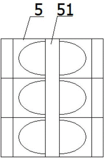
[0021] Such as image 3 As shown, the cross-section of the bearing cap casting 5 to be processed is T-shaped, with finished bearing caps on both sides and waste in the middle, that is, the sprue 51. In order to ensure reliable operation of the device, the thickness of the sprue 51 should be smaller than the thickness of the bearing cap. .

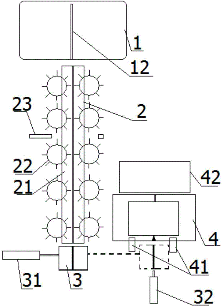
[0022] The engine bearing cap cutting device includes a monolithic mechanism 1, a transmission mechanism 2, a feeding mechanism 3 and a cutting mechanism 4. The structure of each component is described in detail below;

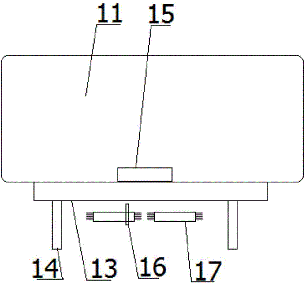
[0023] The whole material mechanism 1 is provided with a material frame 11 for placing the bearing cap casting 5, and the bottom surface of the material frame 11 is provided with a positioning groove 12, and the positioning groove 12 is a through hole structure, which is used to adjust the position of the bearing cap casting 5, and the width of the positioning groove 12 It is larger than the thickness of the sprue 51 and sm...


PUM


Abstract

The invention discloses a cutting device for engine bearing covers. The cutting device comprises an arranging mechanism, a conveying mechanism, a feeding mechanism and a cutting mechanism. The cutting device has the advantages of being reliable in working, convenient and fast to use, capable of achieving automatic operation and free of manual control, improving working efficiency and lowering the labor cost.

Description

technical field [0001] The invention relates to a cutting device for engine bearing cap castings. Background technique [0002] The engine bearing cap is formed by casting, and multiple bearing caps are cast at the same time (such as image 3 shown), so that after casting, it is necessary to cut off the sprue, so as to separate multiple castings, and carry out the next finishing process. [0003] At present, the cutting process is mostly completed by a cutting mechanism installed on the press. The cutting mechanism has a groove for placing the sprue for positioning the casting. After fixing, the cutting knife (with two parallel blades) above the press cuts the casting. On both sides of the sprue of the casting, thereby separating the bearing cap, and the cut sprue falls into the groove. When the equipment is working, a worker needs to operate the press continuously, pick and place the casting and the cut bearing cap, At the same time, it is necessary to regularly collect wa...

Claims


Application Information

Patent Timeline
Patent Type & Authority Applications(China)
IPC IPC(8): B22D31/00
Inventor 宁世玉方金春钟建张金仓
Owner WUHU CHENGTUO AUTO PARTS
Why Eureka
Try Eureka