Positioning tool clamp for precision box-shaped sensor welding and using method of positioning tool clamp for precision box-shaped sensor welding

A positioning tooling and sensor technology, applied in the field of welding tooling fixtures, can solve problems such as inaccurate positioning, relative slippage of components, poor installation visibility, etc., and achieve the effects of avoiding damage, preventing relative slippage, and facilitating observation and adjustment

Active Publication Date: 2015-08-26
TIANJIN UNIV
View PDF9 Cites 4 Cited by
  • Summary
  • Abstract
  • Description
  • Claims
  • Application Information

AI Technical Summary

Problems solved by technology

At present, the positioning fixture used by the production unit has poor installation visibility and inaccurate positioning, and the relative slippage of the components will occur during the clamping process, which cannot guarantee the welding positioning accuracy requirements of the box-type sensor components, and the geometric dimensions of the components after welding have large deviations. , the product qualification rate is low

Method used


Image

  • Positioning tool clamp for precision box-shaped sensor welding and using method of positioning tool clamp for precision box-shaped sensor welding
  • Positioning tool clamp for precision box-shaped sensor welding and using method of positioning tool clamp for precision box-shaped sensor welding
  • Positioning tool clamp for precision box-shaped sensor welding and using method of positioning tool clamp for precision box-shaped sensor welding

Examples


Embodiment Construction

[0027] In order to make the purpose, technical solution and advantages of the present invention clearer, the implementation manners of the present invention will be further described in detail below.

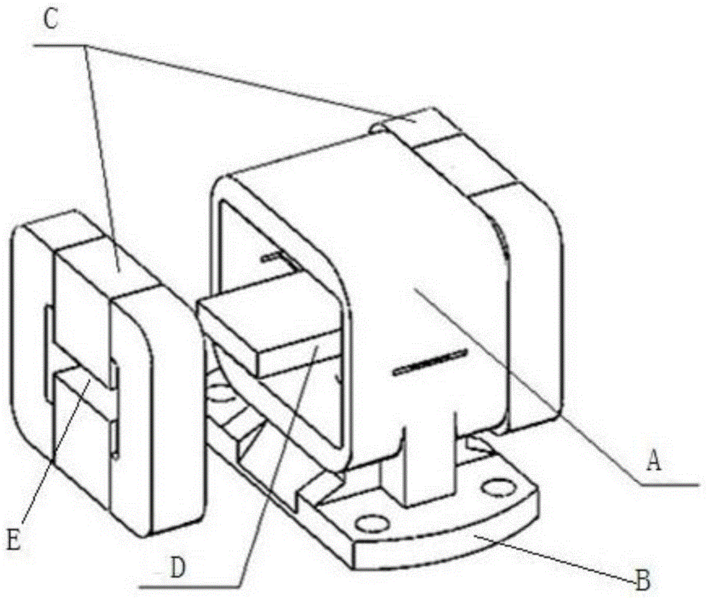
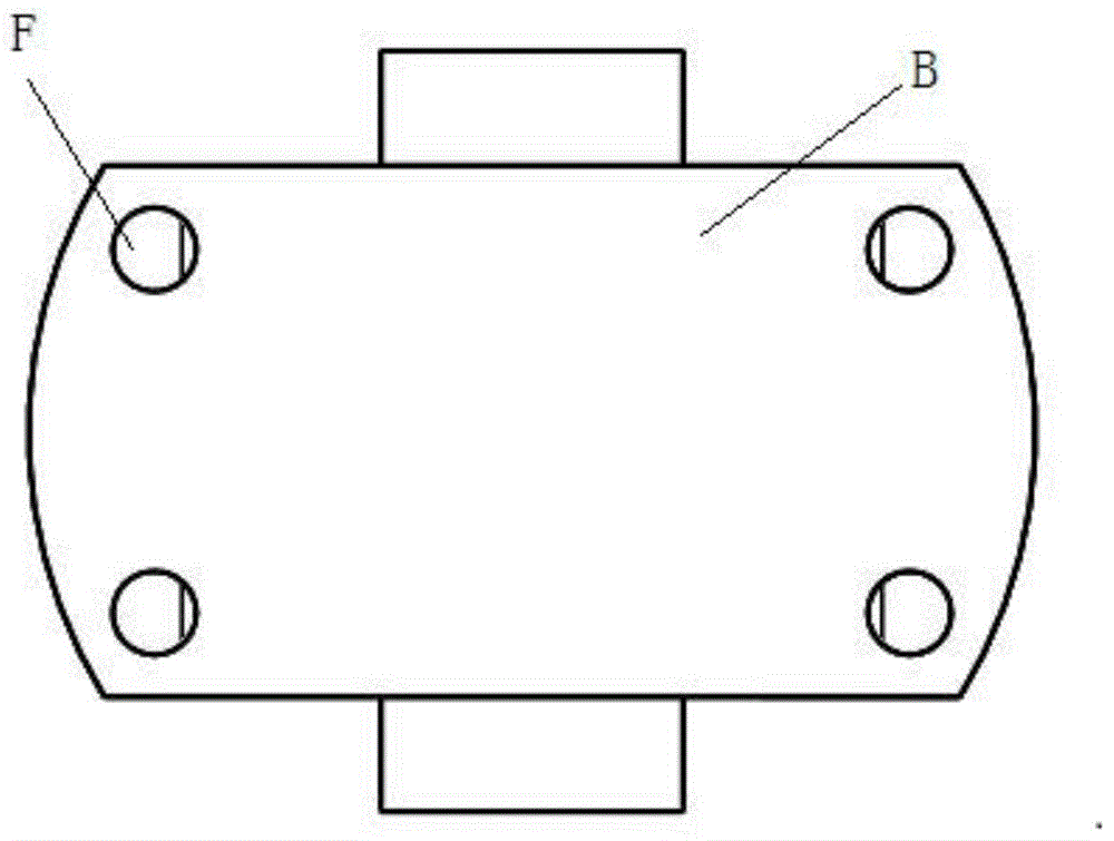
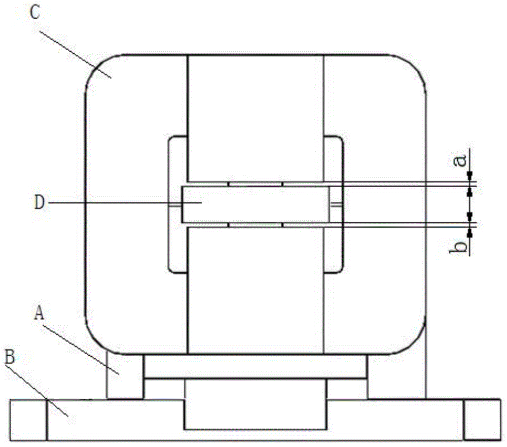
[0028] as attached figure 1 As shown in -3, the existing box-type sensor is composed of a body A, a base B, a cover plate assembly C and an extension plate D, and the extension plate D extends into the middle hole E of the cover plate assembly C, and is connected with the The gap width of the upper and lower edges is the same, and the error is not more than ±0.02mm. This requires that in the spot welding connection between the cover assembly C and the body A, the relevant components of the box-type sensor should be adjusted and fixed in advance according to the error requirements.

[0029] as attached Figure 4 As shown in -5, the positioning fixture of this patent includes an upper plate 1, a middle plate 2, a lower plate 3, a guide rail sleeve 4, a column 5, a heat dissipati...


PUM


Abstract

The invention discloses a positioning tool clamp for precision box-shaped sensor welding and a using method of the positioning tool clamp for precision box-shaped sensor welding. An observation window is arranged in the center of an upper plate; radiating clamping devices are arranged at the positions, on the periphery of the observation window, on the lower surface of the upper plate, a stand column penetrates through a guide rail sleeve and penetrates through the upper plate, a middle plate and a lower plate, the two ends of the stand column are fixed to the upper plate and the lower plate respectively, and a spring is arranged at the position, between the vertical part of the middle plate and the vertical part of the lower plate, of the stand column. Compared with the prior art, according to the technical scheme, the spring, a rapid clamp and the radiating clamping devices are jointly matched to complete clamping of a box-shaped sensor body and a cover plate assembly, and therefore relative slippage of the box-shaped sensor body and the cover plate assembly can be avoided; the radiating clamping devices are adopted, heat conduction in the welding process can be achieved while the clamping force is used, and therefore damage of welding heat to a box-shaped sensor is avoided; the direct observation window is arranged, the size required by welding is conveniently observed and adjusted.

Description

technical field [0001] The invention relates to a welding fixture, in particular to a positioning fixture for precision box-type sensor welding and a method for using the same. Background technique [0002] A precision box-shaped structure sensor is often a high-precision component sensor that can be used to detect information such as displacement, velocity, force, and acceleration. Sensor components are often machined multiple times from a variety of materials. The quality of the welding and forming of the final box-shaped component is directly related to the system accuracy and technical parameters of the entire sensor. At present, the positioning fixture used by the production unit has poor installation visibility and inaccurate positioning, and the relative slippage of the components will occur during the clamping process, which cannot guarantee the welding positioning accuracy requirements of the box-type sensor components, and the geometric dimensions of the component...

Claims


Application Information

Patent Timeline
Patent Type & Authority Applications(China)
IPC IPC(8): B23K37/04
CPCB23K37/0443
Inventor 胡绳荪宋昆阳申俊琦
Owner TIANJIN UNIV
Why Eureka
Try Eureka