Vacuum clamp

A technology of vacuum clamps and fixtures, used in manufacturing tools, workpiece clamping devices, etc., can solve the problems of gas leakage, unstable clamping, silicon wafer fragments, etc., and achieve the effect of safe clamping

Active Publication Date: 2015-08-26
ACM RES SHANGHAI
View PDF12 Cites 11 Cited by
  • Summary
  • Abstract
  • Description
  • Claims
  • Application Information

AI Technical Summary

Problems solved by technology

[0004] However, the second groove of the above-mentioned vacuum fixture is a connected ring structure, and the second sealing ring 340 matched with the second groove is also a connected ring structure. Once a gas leakage point appears on the second sealing ring 340 , will cause gas leakage in the entire second sealing ring 340, resulting in silicon wafer clamping failure or unstable clamping
In addition, it is difficult for the above-mentioned vacuum fixture to adjust the gas pressure difference between the upper and lower planes of the silicon wafer. When the vacuum fixture clamps an ultra-thin silicon wafer, if the vacuum degree in the first sealing ring and the second sealing ring is too high, the silicon If the chip is subjected to a large pressure difference, it will cause silicon chip fragments

Method used


Image

  • Vacuum clamp
  • Vacuum clamp
  • Vacuum clamp

Examples


Embodiment Construction

[0013] In order to describe the technical content, structural features, achieved goals and effects of the present invention in detail, the following will be described in detail in conjunction with the embodiments and accompanying drawings.

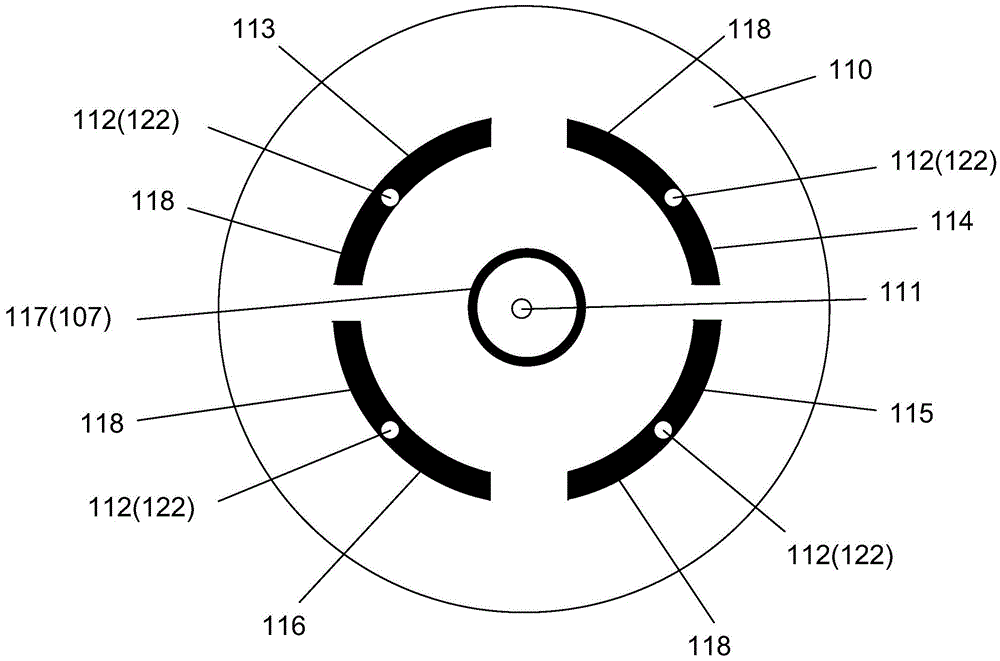
[0014] refer to figure 1 , reveals a bottom view of the vacuum fixture of the present invention. A vacuum fixture according to a representative embodiment of the present invention includes a fixture body 110. The fixture body 110 has a front surface and a back surface opposite to the front surface. The front surface of the fixture body 110 is arranged opposite to the silicon wafer. The groove 107 , the inner groove 107 is an annular groove, and the inner groove 107 is arranged adjacent to the center of the clamp body 110 . A vacuum channel 111 is opened on the fixture body 110 surrounded by the inner groove 107 , and the vacuum channel 111 runs through the front and back of the fixture body 110 . The front of the fixture body 110 is als...


PUM


Abstract

The invention discloses a vacuum clamp. The vacuum clamp comprises a clamp body, wherein multiple grooves are formed in the clamp body, each groove is an independent groove area, a first vacuum hole penetrating through the clamp body is formed in each groove, a sealing part is arranged in each groove, a second vacuum hole is formed in each sealing part and communicated with the first vacuum hole of the corresponding groove, each first vacuum hole is connected with a pipeline structure, and each pipeline structure comprises an exhaust pipeline and a gas inlet pipeline. The mutually independent grooves are formed, so that even if vacuum leakage happens to one of the grooves, the vacuum clamp cannot be influenced when used for clamping a silicon wafer. Besides, the gas inlet pipelines are arranged, accordingly, the gas pressure difference between an upper plane and a lower plane of the silicon wafer can be adjusted, and the vacuum clamp can clamp an ultrathin silicon wafer stably and safely.

Description

technical field [0001] The invention relates to a silicon wafer clamping device, in particular to a vacuum clamp. Background technique [0002] In the manufacturing process of semiconductor devices, silicon wafer clamping devices are usually used to position and clamp the silicon wafers used to manufacture semiconductor devices to complete corresponding process processing, inspection or transfer silicon wafers between different chambers. Among them, the vacuum clamp is widely used in the manufacturing process of semiconductor devices as a commonly used silicon wafer clamping device. The vacuum clamp realizes the clamping of the silicon wafer by creating a gas pressure difference between the upper and lower planes of the silicon wafer. The fixture can ensure that the silicon wafer is evenly stressed everywhere, so as to avoid deformation of the silicon wafer during the clamping process. [0003] Such as image 3 Shown is a structural schematic diagram of an existing vacuum f...

Claims


Application Information

Patent Timeline
Patent Type & Authority Applications(China)
IPC IPC(8): B25B11/00
CPCB25B11/005
Inventor 贾照伟王坚王晖
Owner ACM RES SHANGHAI
Why Eureka
Try Eureka