Check patentability & draft patents in minutes with Patsnap Eureka AI!

Multi-stop-point single-slide-way sliding groove structure

A technology of multiple stop points and stop grooves, which is applied in the field of multi-stop points and single slideway chute structure, can solve the problems of large pulling force of the microphone cable, difficulty in pulling, recovery, and repositioning of the microphone cable, etc. Achieve the effect of smooth pulling and recovery, increasing the effective pulling length and avoiding misoperation

Inactive Publication Date: 2015-08-26
CHINA ELECTRONICS GREAT WALL CHANGSHA INFORMATION TECH +1
View PDF7 Cites 1 Cited by
  • Summary
  • Abstract
  • Description
  • Claims
  • Application Information

AI Technical Summary

Problems solved by technology

[0004] 1. The outer diameter of the barrel is Φ60. Calculated on the basis of a 1.2-meter telephone microphone line, the barrel can only accommodate 5 turns of the microphone line. Due to the height limit of the barrel, the microphone lines will overlap and overlap. When the microphone line overlaps, it is difficult to pull and recover
[0005] 2. When the utility model with the publication number 203667736U uses the single cycle of the slideway, since there are only 5 turns of microphone wires at the barrel, it can only provide at most 5 stop points
Due to improper use by the user, it is easy to cause the microphone cable to stop again. After the stop is not achieved, pull it out, that is, the function of automatic unlocking
[0006] 3. The outer diameter of the barrel is Φ60. Because the microphone wire is wound tangentially on the barrel, and because the force arm is too small, the initial pulling force required for pulling is relatively large, resulting in excessive pulling force of the microphone wire.

Method used


Image

  • Multi-stop-point single-slide-way sliding groove structure
  • Multi-stop-point single-slide-way sliding groove structure
  • Multi-stop-point single-slide-way sliding groove structure

Examples


Embodiment Construction

[0025] The present invention will be further described below in conjunction with the accompanying drawings and specific embodiments.

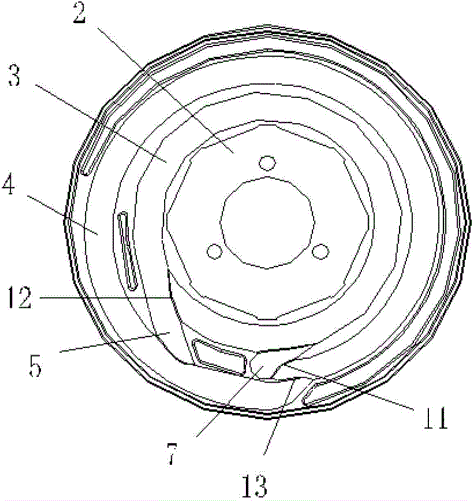
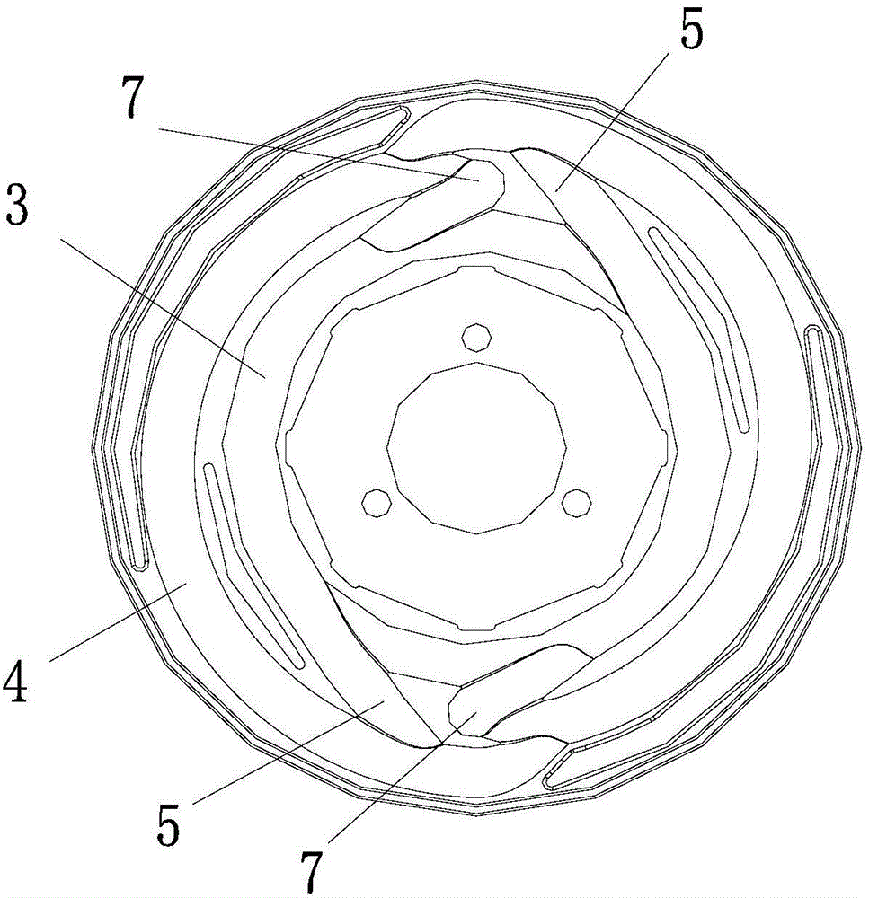
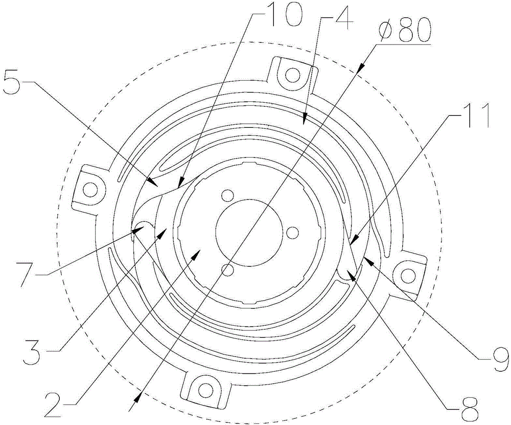
[0026] see image 3 , be provided with inner ring slideway 3 and outer ring slideway 4 on clockwork spring box 2, only be provided with a first step 10 in inner ring slideway 3, the side elevation of first step 10 and clockwork spring The pulling direction is opposite, and the inner ring slideway 3 adopts a slide out slideway 5 to connect with the outer ring slideway 4 at the side elevation of the first step 10, and the outer ring slideway 4 is provided with two second steps 9, each The side facade of the second step 9 is consistent with the tension direction of the mainspring spring, and the mainspring spring box 2 is also provided with two stop grooves between the inner ring slideway 3 and the outer ring slideway 4, namely the first stop groove. The first stop groove 7 and the second stop groove 8, the first stop groove 7 and the second stop...


PUM


Abstract

The invention discloses a multi-stop-point single-slide-way sliding groove structure. A first step (10) is arranged in an inner circle slide way (3), the direction of the side vertical face of the first step (10) is opposite to the tension direction of a spring, and the inner circle slide way (3) is connected with an outer circle slide way (4) through a sliding-out slide way (5) on the side vertical face of the first step (10). At least two second steps (9) are arranged in the outer circle slide way (4). The side vertical face of each second step (9) is parallel to the tension direction of the spring. At least two stop grooves placed between the inner circle slide way (3) and the outer circle slide way (4) are further formed in a spring box (2) and are connected with the inner circle slide way (3). Joint steps (11) are arranged beside the stop grooves. The slope of each joint step (11) is connected with the outer circle slide way (4), and the lower portion of each joint step (11) is connected with the corresponding stop groove. The multi-stop-point single-slide-way sliding groove structure can well avoid misoperation of a user in the using process, and enables pulling recovery to be smooth.

Description

technical field [0001] The invention relates to a chute structure, in particular to a multi-stop-point single-slideway chute structure. Background technique [0002] China with the publication number 203667736U discloses a self-locking and self-releasing take-up device for financial equipment, wherein: figure 1 It is a schematic diagram of a slideway single cycle of the utility model whose publication number is 203667736U. figure 2 It is the double circulation schematic diagram of the slideway of the utility model whose publication number is 203667736U. When the utility model is in use, a clockwork spring with counterclockwise tension is installed in the clockwork spring box 2, and the clockwork spring box 2 is hinged on the base plate, and the inner ring with a rectangular cross section is added to the clockwork spring box 2 to slide Road 3 and outer ring slideway 4, the inner ring slideway 3 and outer ring slideway 4 make the movement of the rotating link pin moving on ...

Claims


Application Information

Patent Timeline
Patent Type & Authority Applications(China)
IPC IPC(8): B65H75/48
Inventor 李洪雷闵红华吴文斌
Owner CHINA ELECTRONICS GREAT WALL CHANGSHA INFORMATION TECH
Features
  • R&D
  • Intellectual Property
  • Life Sciences
  • Materials
  • Tech Scout
  • Unparalleled Data Quality
  • Higher Quality Content
  • 60% Fewer Hallucinations
Learn More