L-shaped oiling machine capable of leading out oil pipe from lower part of machine

A fuel dispenser, L-shaped technology, applied in special distribution devices, packaging, distribution devices, etc., can solve the problems of oil pipe damage, affect the appearance, and the appearance is not beautiful, and achieve high safety performance, uniform and reliable force, and pulling action. Handy effect

Inactive Publication Date: 2015-08-26
JIANGYIN FUREN HIGH TECH
View PDF4 Cites 0 Cited by
  • Summary
  • Abstract
  • Description
  • Claims
  • Application Information

AI Technical Summary

Problems solved by technology

[0002] At present, the oil pipe of the conventional fuel dispenser is led out at the top of the fuel dispenser. In this way, the oil pipe is easy to wear with the fuel dispenser body during the process of drawing out the pipe, thereby causing damage to the oil pipe and causing the appearance of the fuel dispenser to be damaged. The sprayed parts are worn, which affects the appearance; and when the upper outlet pipe is hung, there is always a long section of oil pipe from the top to the bottom of the fuel dispenser and then bent to the point where the fuel gun is hung. Not only is the oil pipe dragged outside for a long time, but the appearance is not beautiful enough

Method used


Image

  • L-shaped oiling machine capable of leading out oil pipe from lower part of machine
  • L-shaped oiling machine capable of leading out oil pipe from lower part of machine
  • L-shaped oiling machine capable of leading out oil pipe from lower part of machine

Examples


Embodiment Construction

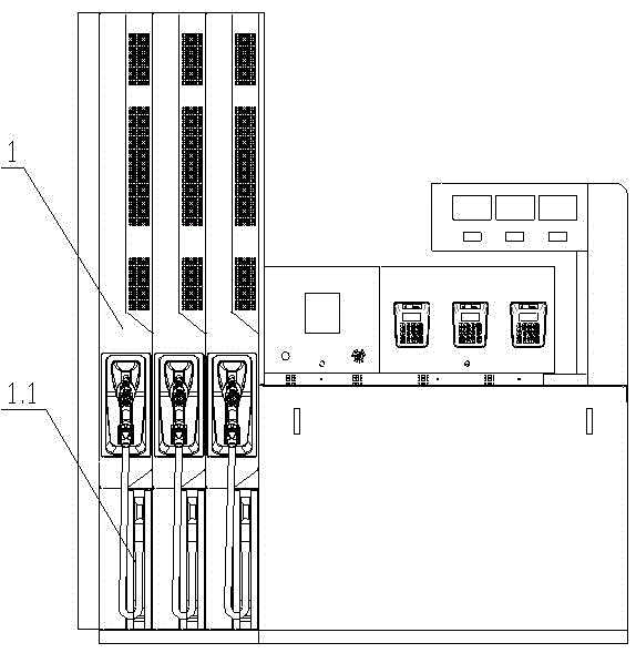
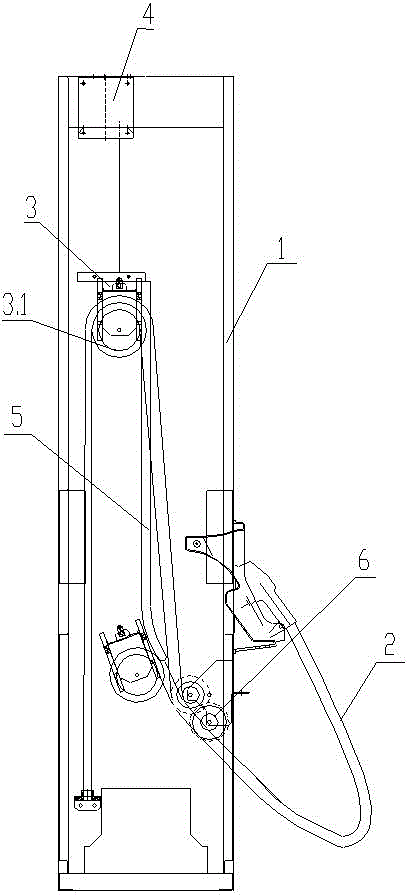
[0022] see Figure 1~4 , the present invention relates to an L-shaped lower pipe refueling machine, the refueling machine includes an organic body 1, a pipe outlet groove 1.1 is arranged under the body 1, and the oil pipe 2 located in the body 1 is led out to the Body 1 outside;

[0023] Specifically, the oil pipe 2 located in the body 1 is hung on the movable pulley 3.1, and the movable pulley 3.1 is hung on the movable pulley bracket 3, and the movable pulley bracket 3 is hung on the rubber hose balancer 4. Preferably, the rubber hose balancer 4 It includes a ratchet and pawl mechanism composed of a ratchet 4.3 and a pawl 4.4. The shaft of the ratchet 4.3 is wound with a wire rope 4.2, and the free end of the wire rope 4.2 is connected with a hook 4.1. The hook 4.1 is hooked on the movable pulley bracket 3; there is a reset spring 4.5 One end is connected to the body 1, and the other end is connected to the ratchet 4.3; when the oil pipe 2 is pulled outward, the oil pipe 2 ...


PUM


Abstract

The invention relates to an L-shaped oiling machine capable of leading out an oil pipe from the lower part of the machine. The oiling machine comprises an oiling machine body (1), wherein pipe outlet grooves (1.1) are formed in the lower part of the oiling machine body (1); an oil pipe (2) in the oiling machine body (1) is led out of the oiling machine body (1) through the outlet pipe grooves (1.1); the oil pipe (2) in the oiling machine body (1) is hung to a movable pulley (3.1) hung on a movable pulley support (3); the movable pulley support (3) is hung on a rubber tube balancer (4). The L-shaped oiling machine with the downtake pipe is convenient to use, unlikely to wear the oil pipe, and more attractive in appearance.

Description

technical field [0001] The invention relates to a fuel dispenser, in particular to an L-shaped fuel dispenser with a fuel pipe placed below it, and belongs to the technical field of fuel dispensers. Background technique [0002] At present, the oil pipe of the conventional fuel dispenser is led out at the top of the fuel dispenser. In this way, the oil pipe is easy to wear with the fuel dispenser body during the process of drawing out the pipe, thereby causing damage to the oil pipe and causing the appearance of the fuel dispenser to be damaged. The sprayed parts are worn, which affects the appearance; and when the upper outlet pipe is hung up, there is always a long section of oil pipe from the top to the bottom of the fuel dispenser and then bent to the point where the fuel gun is hung. Contents of the invention [0003] The object of the present invention is to overcome the above disadvantages and provide an L-shaped fuel dispenser with a lower pipe. [0004] The purpo...

Claims


Application Information

Patent Timeline
Patent Type & Authority Applications(China)
IPC IPC(8): B67D7/06B65H75/48B65H75/44
Inventor 黄瑞娟陶连跃任都袁君伟庄磊薛正浩戴珉
Owner JIANGYIN FUREN HIGH TECH
Why Eureka
Try Eureka