Volume-type fluid mechanism

A fluid mechanism and volumetric technology, applied in liquid fuel engines, mechanical equipment, machines/engines, etc., can solve problems such as leakage, low efficiency, and short service life of fluid mechanisms

Inactive Publication Date: 2015-08-26
ZEROQ SCI & TECH
View PDF5 Cites 2 Cited by
  • Summary
  • Abstract
  • Description
  • Claims
  • Application Information

AI Technical Summary

Problems solved by technology

However, due to structural reasons, except for the compensation problem of the reciprocating piston fluid mechanism due to the invention of the piston ring, the compensation problem of the rotary fluid mechanism has not been solved, resulting in short life, serious leakage and low efficiency of the existing fluid mechanism. and other problems, so it is necessary to invent a new type of fluid mechanism

Method used


Image

  • Volume-type fluid mechanism
  • Volume-type fluid mechanism
  • Volume-type fluid mechanism

Examples


Embodiment 1

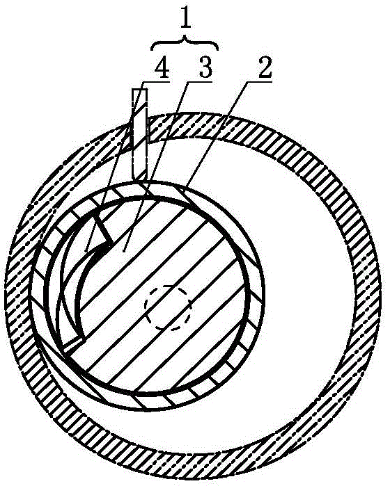
[0152] A volumetric fluid mechanism such as figure 1 As shown, the volumetric fluid mechanism includes an eccentric shaft 1 and a working medium moving part 2, the eccentric shaft 1 includes a drive shaft 3 and a deflection non-sleeve body 4, and the deflection non-sleeve body 4 is arranged on the drive shaft 3 The rotating shaft and / or the deflection non-sleeve body 4 is arranged on the eccentric part of the drive shaft 3 , and the working medium moving part 2 is sleeved on the drive shaft 3 and the deflection non-sleeve body 4 .

[0153] In a specific implementation, the working medium moving part 2, the drive shaft 3 and the deflection sleeve 4 can be combined with a cylinder to form a volumetric fluid mechanism.

Embodiment 2

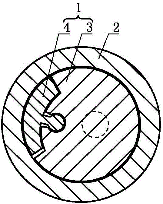
[0155] A volumetric fluid mechanism such as figure 2 As shown, on the basis of Embodiment 1, the deflection non-sleeve body 4 can be further selectively arranged on the rotating shaft of the drive shaft 3 through a hinge structure or on the eccentricity of the drive shaft 3 through a hinge structure. department.

[0156] As a changeable implementation mode, in Embodiment 1 and Example 2 and their changeable implementation forms, the deflection non-sleeve body 4 can be further set as an eccentric deflection non-sleeve body or as a non-eccentric deflection non-sleeve body. body.

Embodiment 3

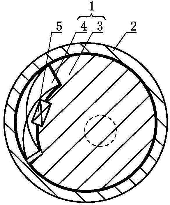
[0158] A volumetric fluid mechanism such as image 3 As shown, on the basis of Embodiment 1, further optionally between the deflection non-sleeve body 4 and the shaft of the drive shaft 3 and / or between the deflection non-sleeve body 4 and the drive shaft A rotation angle control device 5 is arranged between the eccentric parts of 3.

[0159] As a transformable embodiment, in Embodiment 1 and Embodiment 2 and their transformable embodiments, it is possible to further select between the deflection non-sleeve body 4 and the rotating shaft of the drive shaft 3 and / or a rotation angle control device 5 is provided between the deflection sleeve 4 and the eccentric part of the drive shaft 3 .


PUM


Abstract

The invention provides a volume-type fluid mechanism which comprises an eccentric shaft and a working medium moving part, wherein the eccentric shaft comprises a driving shaft and a deflection non-sleeve body; the deflection non-sleeve body is arranged on the rotating shaft of the driving shaft and/or arranged on the eccentric part of the driving shaft; and the working medium moving part sleeves the driving shaft and the deflection non-sleeve body. According to the volume-type fluid mechanism provided by the invention, the compensation problem of the mechanism is effectively solved, the life of the volume-type fluid mechanism is prolonged, the sealing performance of the volume-type fluid mechanism is effectively improved and the efficiency is improved.

Description

technical field [0001] The invention relates to the field of thermal energy and power, in particular to a volumetric fluid mechanism. Background technique [0002] Volumetric fluid mechanism is a very important mechanism, which is an important mechanism for liquid pumps, liquid motors, gas compressors, gas expansion mechanisms and engines. However, due to structural reasons, except for the compensation problem of the reciprocating piston fluid mechanism due to the invention of the piston ring, the compensation problem of the rotary fluid mechanism has not been solved, resulting in short life, serious leakage and low efficiency of the existing fluid mechanism. Problems such as, therefore need to invent a kind of novel fluid mechanism. Contents of the invention [0003] In order to solve the above problems, the technical scheme proposed by the present invention is as follows: [0004] Scheme 1: A volumetric fluid mechanism, the volumetric fluid mechanism includes an eccent...

Claims


Application Information

Patent Timeline
Patent Type & Authority Applications(China)
IPC IPC(8): F04C2/356F04C2/344F04C2/44F04C2/46F04C2/10F04C2/02F04C18/356F04C18/344F04C18/44F04C18/46F04C18/10F04C18/02F03C2/30F03C2/22F03C2/02F01C1/356F01C1/344F01C1/44F01C1/46F01C1/10F01C1/02
CPCF04C18/356
Inventor 靳北彪
Owner ZEROQ SCI & TECH
Why Eureka
Try Eureka