Harmonic-wave speed reducer with improved structure

A harmonic reducer, rigid wheel technology, applied in mechanical equipment, belts/chains/gears, transmissions, etc., can solve problems such as the difficulty of widespread use of harmonic reducers, to eliminate the possibility of failure, load capacity and The effect of enhanced impact resistance and convenient installation and use

Inactive Publication Date: 2015-08-26
上海鑫君传动科技有限公司
View PDF5 Cites 14 Cited by
  • Summary
  • Abstract
  • Description
  • Claims
  • Application Information

AI Technical Summary

Problems solved by technology

A series of problems make it difficult for the harmonic reducer with double rigid wheel structure to be widely used

Method used


Image

  • Harmonic-wave speed reducer with improved structure
  • Harmonic-wave speed reducer with improved structure
  • Harmonic-wave speed reducer with improved structure

Examples


Embodiment Construction

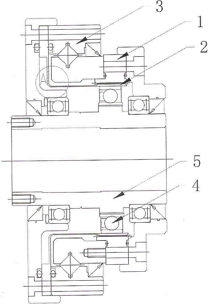
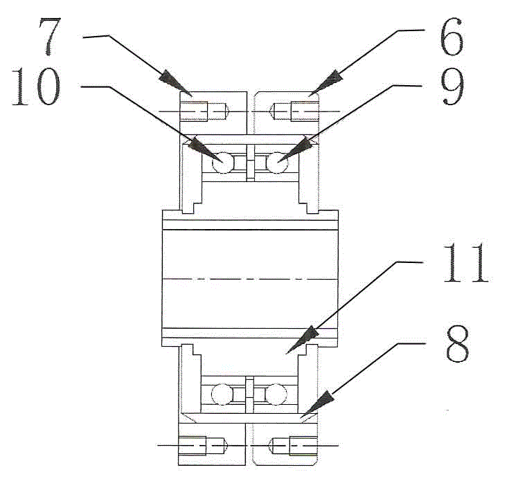
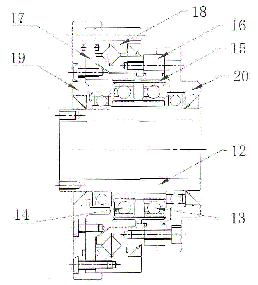
[0018] An improved structure harmonic speed reducer has a double rigid wheel structure, and the flexible wheel is in the shape of a ring. It has main components: elliptical wave generator 12, flexible bearing 13, flexible bearing 14, flexible wheel 15, rigid wheel 16, rigid wheel 17, cross roller bearing 18, front end cover 19 and rear end cover 20. Two identical flexible bearings (13, 14) are mounted on the wave generator 12. The flexible spline 15 is in the shape of a ring, is installed on the outer ring of the flexible bearing, and is bent into an ellipse. The number of internal teeth of the rigid wheel 16 is 2 more than the number of external teeth of the flexible wheel 15, and it is connected with the rear end cover 20 and the inner ring of the cross roller bearing 18 as the fixed end of the harmonic reducer. The number of internal teeth of the rigid wheel 17 is the same as the number of external teeth of the flexible wheel 15, and it is connected with the front end cove...


PUM


Abstract

The invention discloses a harmonic-wave speed reducer with an improved structure of double rigid wheels. Two identical flexible bearings are mounted onto a wave generator. Flexible wheels are circular ring-shaped and mounted onto outer rings of the flexible bearings. The number of internal teeth of a first rigid wheel is greater than that of external teeth of each flexible wheel by two. The first rigid wheel, a rear end cover and an inner ring of a criss-cross roller bearing are connected together as a fixing end of the harmonic-wave speed reducer. The number of internal teeth of a second rigid wheel is the same as that of external teeth of each flexible wheel. The second rigid wheel, a front end cover and an outer ring of the criss-cross roller bearing are connected together as an output end of the harmonic-wave speed reducer.The harmonic-wave speed reducer with the improved structure has a reasonable structure and high load-carrying and impact-resisting capabilities.

Description

technical field [0001] The invention relates to a harmonic reducer. Background technique [0002] The harmonic reducer has the characteristics of high precision, small size and high load torque, and is widely used in the field of industrial robots. figure 1 It is a simplified structural diagram of a traditional harmonic reducer, which has five core components: rigid wheel 1, flexible wheel 2 (flexible wheel can be cup-shaped or hat-shaped), cross roller bearing 3, flexible bearing 4 and elliptical wave Generator 5. The elliptical wave generator 5 is usually used as the input end, the rigid wheel 1 is used as the fixed end, and the flexible wheel 2 is used as the output end. The flexspline 2 is bent into an ellipse by the wave generator 5, and the external teeth of the flexspline 2 mesh with the internal teeth of the rigid spline 1 at both ends of the ellipse in the long axis direction. For the gear meshing state of the harmonic reducer, see figure 2 . [0003] The torq...

Claims


Application Information

Patent Timeline
Patent Type & Authority Applications(China)
IPC IPC(8): F16H49/00
CPCF16H49/001
Inventor 顾京君
Owner 上海鑫君传动科技有限公司
Why Eureka
Try Eureka