System and method for overhead line fault location and monitoring

A technology for fault location and overhead lines, applied in fault locations, information technology support systems, and electrical measurement, can solve problems such as unsafe communication, low accuracy, time-consuming and labor-intensive equipment and methods, and achieve safety and fault resolution. The detection is accurate and reliable, and the effect of overcoming inaccuracy

Inactive Publication Date: 2015-08-26
国网山东济南市历城区供电公司 +1
View PDF9 Cites 24 Cited by
  • Summary
  • Abstract
  • Description
  • Claims
  • Application Information

AI Technical Summary

Problems solved by technology

[0007] In order to solve the above defects in the prior art, the present invention provides an overhead line fault location monitoring system and method, which solves a s

Method used


Image

  • System and method for overhead line fault location and monitoring
  • System and method for overhead line fault location and monitoring
  • System and method for overhead line fault location and monitoring

Examples


Embodiment Construction

[0036] The specific implementation of the present invention will be described below in conjunction with the accompanying drawings. It should be understood that the implementation examples described here are only used to illustrate and explain the present invention, and are not intended to limit the present invention.

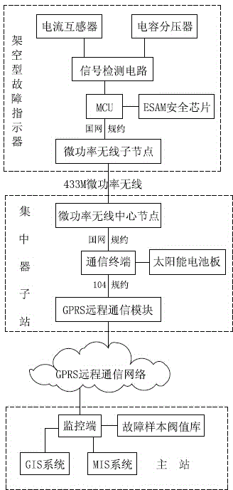
[0037] Such as figure 1 The overhead line fault location monitoring system shown includes a fault indicator, a concentrator substation and a main station.

[0038] The fault indicator includes MCU, current transformer, capacitive voltage divider, signal detection circuit, ESAM safety chip and micro-power wireless sub-node.

[0039] Overhead Line Fault Indicators utilize the principle of CT (Current Transformer) to measure line current. When the overhead line fault indicator is hung on the wire, the primary current will flow through the current sensor of the overhead line fault indicator, and the current sensor will generate a CT secondary signal, which is filte...


PUM


Abstract

The invention provides a system and a method for overhead line fault location and monitoring. The system comprises a fault indicator, a concentrator substation, and a main station. The fault indicator comprises a MCU, a current transformer, a capacitance voltage divider, a signal detection circuit, an ESAM security chip, and a micropower wireless sub-node. The concentrator substation comprises a communication terminal, a micropower wireless center node, and a GPRS remote communication module. The main station comprises a GIS system, a MIS system, and a monitoring terminal. The method comprises the following steps: acquiring and calculating current and voltage signals; determining short circuit faults, and determining grounding faults through a seventh harmonic and first half wave method; and marking fault places and notifying inspection tour personnel. The system and the method are accurate in determination, good in anti-interference capability, high in security, and can effectively assist power grid maintenance operation, thereby improving power grid automation level.

Description

technical field [0001] The invention relates to power grid automation technology, in particular to an overhead line fault location monitoring system and method. Background technique [0002] Distribution network automation has greatly improved the reliability and quality of power supply, shortened the time for handling accidents, and reduced the scope of power outages. However, at present, power distribution terminals (FTU / DTU / TTU) are generally deployed at the position of switches or transformers. Due to the lack of management and control in the middle section, when the transmission distance of the distribution line is long, the line has many branches, the operation is complicated, and the environment and weather conditions are relatively harsh, line short circuits and ground faults caused by natural disasters such as external breakage, equipment failure, and lightning often occur. Moreover, when a fault occurs, it is difficult to determine the fault section (location),...

Claims


Application Information

Patent Timeline
IPC IPC(8): G01R31/02G01R31/08
CPCY04S10/52
Inventor 张健李茂林李超战晓蕾高峰
Owner 国网山东济南市历城区供电公司
Why Eureka
Try Eureka