Echo planar imaging method and device

An echo-planar imaging and imaging technology, which is used in measurement devices, measurement of magnetic variables, instruments, etc., can solve problems such as uneven distribution, uneven intensity distribution, and inability to obtain information, and achieve the effect of ensuring uniform distribution.

Active Publication Date: 2015-08-26
SHANGHAI UNITED IMAGING HEALTHCARE
View PDF5 Cites 12 Cited by
  • Summary
  • Abstract
  • Description
  • Claims
  • Application Information

AI Technical Summary

Problems solved by technology

However, when the eddy current response of each gradient axis is different, the time delay is different, or the gradient amplifier has nonlinear characteristics, N/2 artifacts ( Nyquist Ghost)
Because it comes from the

Method used


Image

  • Echo planar imaging method and device
  • Echo planar imaging method and device
  • Echo planar imaging method and device

Examples


Embodiment Construction

[0039] The present invention will be further described below in conjunction with the accompanying drawings and embodiments.

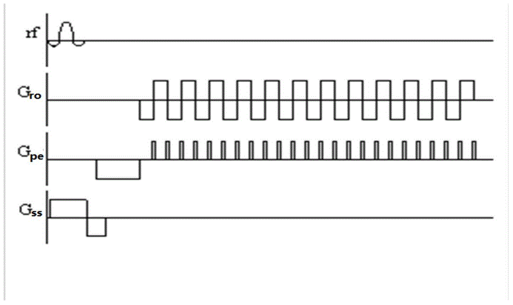
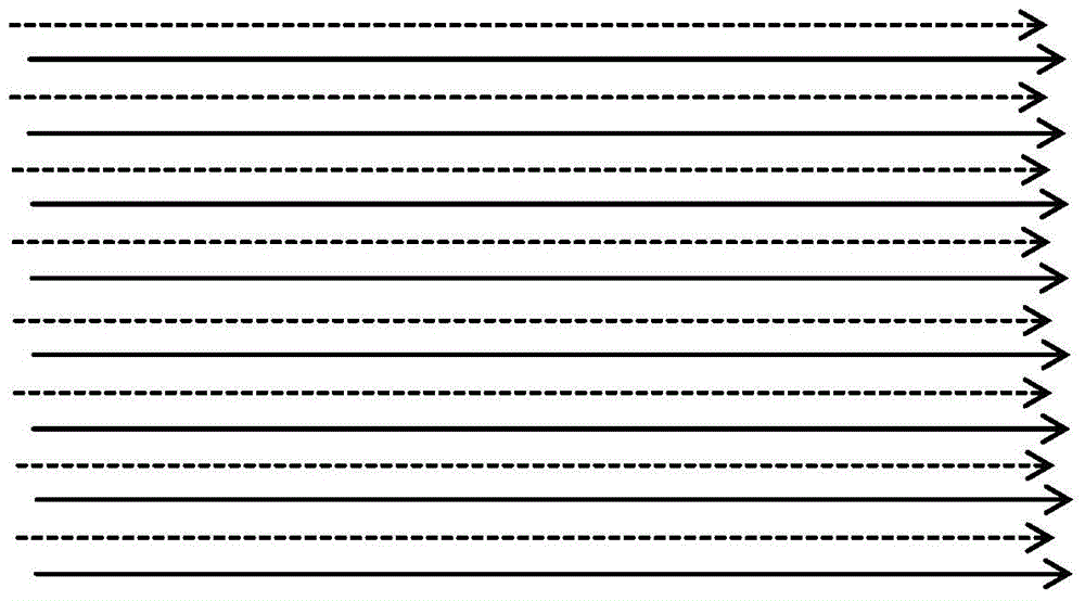
[0040] figure 1 Schematic diagram of the echo-planar imaging (EPI) sequence during non-tilted scanning. Gro, Gpe, and Gss are readout, phase encoding, and layer selection gradients, respectively. The K-space data collected in echo-planar imaging is continuously collected using the positive and negative polarities of the readout gradient, so as to achieve the effect of fast imaging. The k-space signal was acquired during the plateau of the readout gradient. figure 2 is the K-space of the echo-planar imaging (EPI) sequence when the scan is not tilted. When the scan is not tilted, the phase encoding gradient will not have a jump of parity, and the K-space data is evenly distributed in the phase encoding direction.

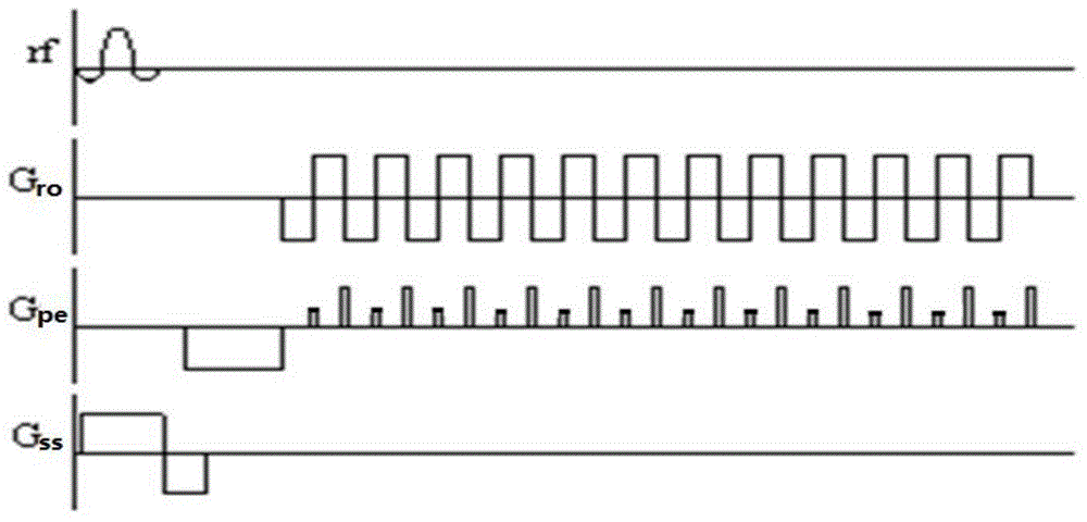
[0041] image 3 It is a schematic diagram of an echo-planar imaging (EPI) sequence during oblique scanning, and there are odd-even jumps...


PUM


Abstract

An echo planar imaging method comprises the following steps of: applying an echo planar imaging sequence, obtaining pre-scanning K space data after a pre-scanning progress, grouping the pre-scanning K space data to obtain odd number data line and even number data line K spaces, and respectively integrating the odd number data line and even number data line K spaces and carrying out the Fourier transformation to obtain an image domain data Iodd of odd number data lines and an image domain data Ieven of even number data lines; carrying out operation on the image domain data Iodd and Ieven, and obtaining a phase difference change rate [lambda] along a phase encoding direction; obtaining a phase difference scope [phi] of an imaging visual field FOV; obtaining offset data in the phase encoding directions of the K space odd number data lines and even number data lines, and carrying out phase encoding gradient compensation on the echo planar imaging sequence according to the offset data; carrying out formal scanning on the compensated echo planar imaging sequence, and obtaining imaging K space data; and carrying out the Fourier transformation to obtain an image. The invention further discloses a echo planar imaging device.

Description

【Technical field】 [0001] The invention relates to magnetic resonance imaging technology, in particular to a planar echo imaging method and device. 【Background technique】 [0002] Echo Plane Imaging (EPI) technology is widely used because of its sampling speed. At the same time, its application range is limited because of the interference of N / 2 artifacts in the generated image. Generally, reference correction is performed on echo-planar imaging data to eliminate or reduce artifact interference by using the method of acquiring reference data before imaging data. However, when the eddy current response of each gradient axis is different, the time delay is different, or the gradient amplifier has nonlinear characteristics, N / 2 artifacts ( Nyquist Ghost). Because it comes from the uneven distribution of K space in the phase encoding direction, and the reference data cannot obtain the information in the phase encoding direction dimension, this artifact cannot be eliminated by ...

Claims


Application Information

Patent Timeline
IPC IPC(8): G01R33/561
Inventor 宋瑞波张卫国
Owner SHANGHAI UNITED IMAGING HEALTHCARE
Why Eureka
Try Eureka