Large-size object laser radar imaging technology

A lidar imaging and lidar technology, applied in the field of radar imaging to achieve the effect of effective technical support

Inactive Publication Date: 2015-08-26
王明军 +1
View PDF1 Cites 3 Cited by
  • Summary
  • Abstract
  • Description
  • Claims
  • Application Information

AI Technical Summary

Problems solved by technology

[0011] The purpose of the present invention is to provide large-scale target laser radar imaging technology simulation, which solves the problem that there is no research on laser scattering one-dimensional imaging and its range Doppler scattering characteristics in China.

Method used


Image

  • Large-size object laser radar imaging technology
  • Large-size object laser radar imaging technology
  • Large-size object laser radar imaging technology

Examples


Embodiment Construction

[0030] The present invention will be described in detail below in combination with specific embodiments.

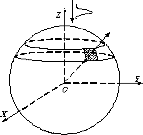
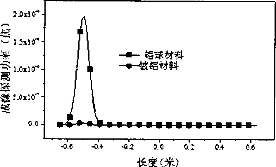
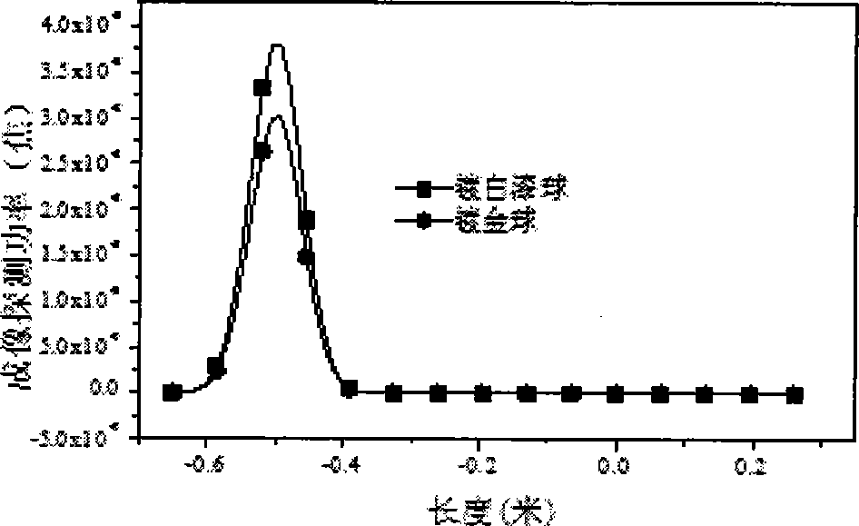
[0031] The method of the present invention first constructs the total scattering power equation of the laser radar. When a narrow pulse is incident, the narrow pulse wave distribution of the target echo is equivalent to the sum of the sub-echoes of the three-dimensional target scattering points. The projection of the vector sum on the radar ray, that is, the sub-echoes in the same range unit are added as a vector, and the target echo pulse amplitude distribution is usually called a one-dimensional real range image, or one-dimensional range image for short. One-dimensional laser range imaging is that after the laser pulse is incident on the target, the three-dimensional target surface mirror reflects point echoes, and coherently superimposes them in the detection direction of the detector. The distribution of the echo amplitude on the detector is called the target laser one...


PUM


Abstract

The invention discloses large-size object laser radar imaging technology simulation. The technical scheme provided by the invention comprises steps of firstly constructing a total scattering power equation of a laser radar, wherein the equation is that Ps(t) = Pc(t) + Pf(t), Ps(t) represents the total scattering power, Pc(t) represents the coherent scattering power, and Pf(t) represents the non-coherent scattering power; and performing laser one-dimensional range profile simulation on a spherical object or a tapered object. The beneficial effects of the technology simulation are that beneficial technology supplements and effective technology supports are provided for experiment tests or laser radar engineering applications through the large-size object laser radar imaging technology simulation.

Description

technical field [0001] The invention belongs to the technical field of radar imaging and relates to a large-size target laser radar imaging technology. Background technique [0002] Laser scattering imaging of large-scale targets is an important imaging technology in the fields of civil industry, national defense and aerospace. Laser imaging includes the intensity image of the target in the detection direction and the distance image projected along the line of sight of the target. Laser scattering three-dimensional coherent imaging technology has important military and civilian application prospects. Laser scattering distance imaging technology uses narrow pulse laser beams to irradiate complex targets to generate target two-dimensional intensity distribution and three-dimensional information of one-dimensional range images. Coherent detection of scattered echoes with different detector distances, obtaining the echo intensity, range image and relative radial distance of co...

Claims


Application Information

Patent Timeline
Patent Type & Authority Applications(China)
IPC IPC(8): G01S7/497G01S17/89
CPCG01S7/497G01S17/89
Inventor 王明军弓树宏吴振森曹运华
Owner 王明军
Why Eureka
Try Eureka