Ethernet fault positioning and detection method
A fault location and detection method technology, applied in the direction of data exchange network, digital transmission system, electrical components, etc., can solve the problems of inability to adapt to fault detection and low accuracy
Inactive Publication Date: 2015-08-26
STATE GRID CORP OF CHINA +1
View PDF3 Cites 11 Cited by
- Summary
- Abstract
- Description
- Claims
- Application Information
AI Technical Summary
Problems solved by technology
[0007] The purpose of the present invention is to overcome the deficiencies of the prior art, and provide a method for Ethernet fault location and detection, to solve the problem that the accuracy of the existing network fault detection method is low, and it is necessary to modify node codes and control node behavior to realize fault detection. Unable to adapt to the fault detection of Ethernet devices such as switches that are not modifiable
Method used
View moreImage
Smart ImageViewing Examples
Examples
Embodiment 1
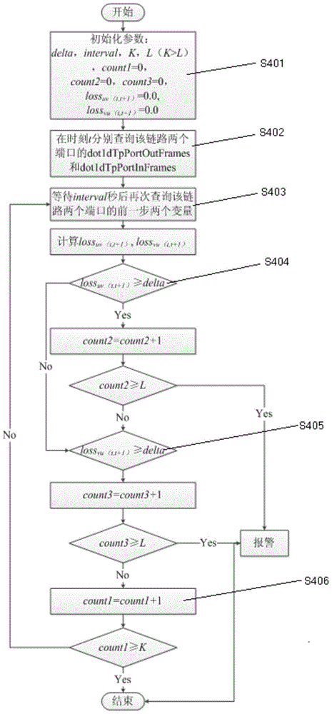
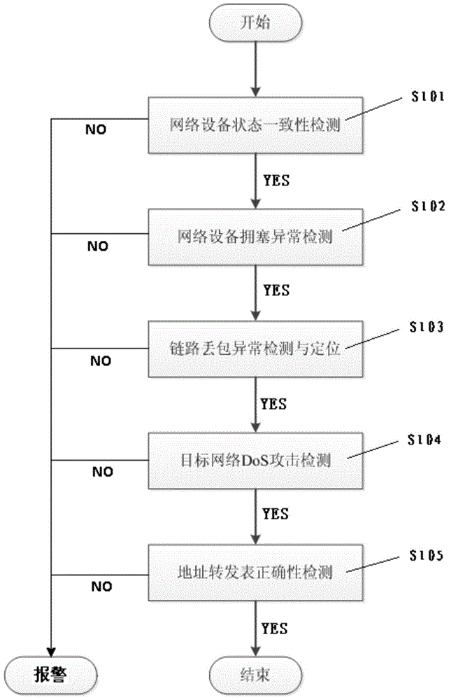
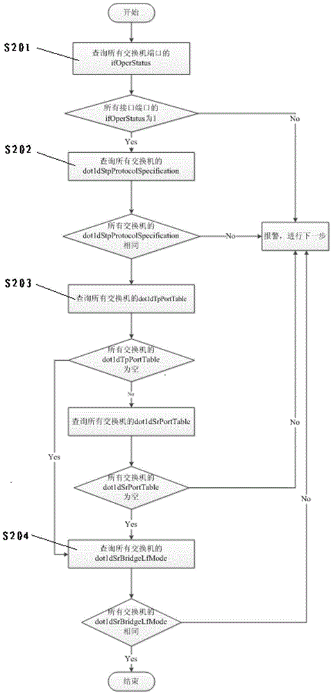
[0059] An Ethernet fault location and detection method provided in this embodiment has the following functions: Figure 1~6 The flow chart shown is used to locate and detect the failure of network equipment in the target network. The overall flow chart is as follows figure 1 shown, including the following steps:
Login to View More PUM
 Abstract
The invention discloses an Ethernet fault positioning and detection method which is used for positioning and detecting faults of network devices in a target network. The method comprises the following steps: network device state consistency detection, network device congestion abnormity detection, link packet loss abnormity detection and positioning, target network DoS attack detection and address forwarding table correctness detection. Compared with the prior art, the Ethernet fault positioning and detection method can detect and position Ethernet faults by searching standardization-based switch-supported SNMP and MIB-2 at present and then by carrying out simple calculation, so that the Ethernet fault positioning and detection method is simple and practical, has better applicability and engineering applicability, and has higher efficiency and accuracy.
Description
technical field [0001] The invention relates to the technical field of network system fault maintenance, in particular to a method for locating and detecting Ethernet faults. Background technique [0002] As more and more Internet applications are integrated into people's daily life, people have higher and higher requirements for network user experience. Keeping the network unblocked in real time is a prerequisite for ensuring user experience. Therefore, it is necessary to detect, locate and eliminate network faults in a timely manner. Therefore, the detection and removal of network faults is a very important part of network management. Therefore, how to efficiently and accurately locate and detect network faults has become a hot and difficult point in network fault research in recent years. [0003] At present, the main methods of Ethernet fault detection are: establishing a dependency graph or a module dependency graph between network communication entities, and then dete...
Claims
Login to View More Application Information
Patent Timeline
 IPC IPC(8): H04L12/24H04L12/26
Inventor 任水华纪诗厚李祝红赵灿明杜炳
Owner STATE GRID CORP OF CHINA
Features
- R&D
- Intellectual Property
- Life Sciences
- Materials
- Tech Scout
- Unparalleled Data Quality
- Higher Quality Content
- 60% Fewer Hallucinations
Learn More Browse by: Latest US Patents, China's latest patents, Technical Efficacy Thesaurus, Application Domain, Technology Topic, Popular Technical Reports.
© 2025 PatSnap. All rights reserved.Legal|Privacy policy|Modern Slavery Act Transparency Statement|Sitemap|About US| Contact US: help@patsnap.com


