
Standing wave ratio meter for integrated antenna tuner

A technology of integrated circuits and detectors, which can be used in multi-terminal-pair networks, transmission monitoring, electrical components, etc., and can solve problems such as inability to integrate silicon chips.

Active Publication Date: 2015-08-26
TELEFON AB LM ERICSSON (PUBL)
View PDF7 Cites 10 Cited by
  • Summary
  • Abstract
  • Description
  • Claims
  • Application Information

AI Technical Summary

Problems solved by technology

Like the directional coupler, the transformer 26 is a discrete component that is quite large and cannot be integrated into a silicon chip

Method used


Image

  • Standing wave ratio meter for integrated antenna tuner
  • Standing wave ratio meter for integrated antenna tuner
  • Standing wave ratio meter for integrated antenna tuner

Examples


Embodiment Construction

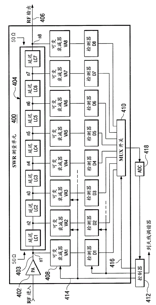
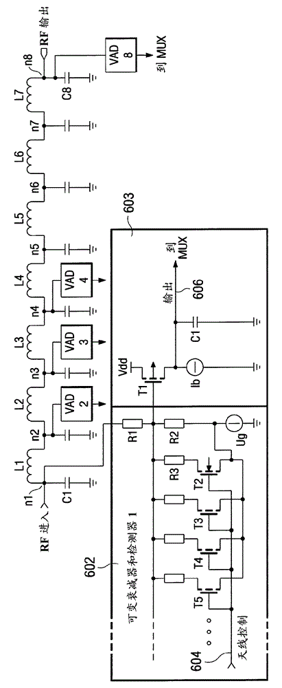
[0036] Referring now to the drawings, wherein like numerals are used herein to refer to like elements throughout, there are shown and described various figures and embodiments of exemplary radio frequency transmission circuits including exemplary SWR measurement circuit architectures. Other possible embodiments are also described. The figures are not necessarily drawn to scale and in some instances the figures are exaggerated and / or simplified in places for illustrative purposes only. Those skilled in the art will recognize the many possible applications and variations based on the following examples of possible embodiments.

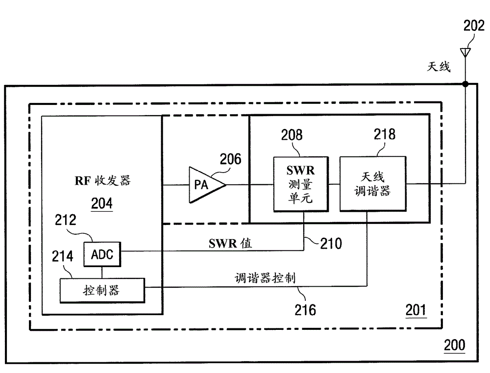
[0037] refer to figure 2 , an electrical block diagram of an exemplary transceiver circuit 200 is provided. A user equipment or base station device transceiver 200 (which includes an exemplary transmission circuit 201 ) may be adapted to be connected to an antenna 202 where RF transmission signals will be transmitted. The transmission circuit 201 may...


PUM


Abstract

The invention provides circuitry integrated into a silicon chip that measures aspects of an RF signal on a transmission line in order to provide data that is ultimately used by an antenna tuner circuit to substantially match the impedance of the antenna with that of the transmission line providing the RF frequency to be transmitted.

Description

technical field [0001] The present invention relates to standing wave ratio (SWR) meters and associated circuitry that may be adapted for incorporation into integrated circuits. In particular, embodiments of the invention relate to transmission circuitry in a mobile device, base station, or other RF transmission device, wherein the transmission circuitry includes standing wave ratio measurement circuitry adapted to provide data or information that can be used to adjust The impedance seen by the transmission antenna is used to improve the impedance match of the antenna to the RF transmission line and thereby help maximize the power output of the RF transmission circuit for various transmission RF frequency channels. Background technique [0002] Typically, the performance of cellular antennas is far from ideal. A significant portion of the transmitter power output is usually reflected back from the antenna due to poor antenna impedance matching. When a single transmit frequ...

Claims


Application Information

Patent Timeline
IPC IPC(8): H04B17/15
CPCH04B17/001H04B1/40H04B17/103H04B17/0007H04B17/10H03H7/40H04B17/12H04B17/13
Inventor J.O.佩汤恩
Owner TELEFON AB LM ERICSSON (PUBL)
Learn More