
Commutator segment manufacturing method

A manufacturing method and commutator piece technology, applied in commutator manufacturing, metal processing equipment, etc., can solve the problems of high production cost, bending of the back of the piece body, low utilization rate of copper materials, etc.

Active Publication Date: 2015-09-02
ZHEJIANG DONGRUI MACHINERY IND
View PDF4 Cites 0 Cited by
  • Summary
  • Abstract
  • Description
  • Claims
  • Application Information

AI Technical Summary

Problems solved by technology

The production of the above-mentioned slot-type commutator segments uses a stamping process, but it will produce a lot of scraps, the utilization rate of copper materials is low, and the production cost is also high. The quality of the type commutator; there is an upsetting process, but because of the need for upper demoulding, the mold cavity must be designed to have a certain taper, which leads to the inclination of the left and right sides of the commutator after cold heading (that is, the upper Thick and thin, which is also a kind of warping and unevenness). In addition, when demoulding, the steps will first leave the mold cavity. Due to the stress, the overhanging end of the steps will bow, causing the back of the sheet (that is, the inner surface of the sheet) ) produce bending, which will seriously affect the quality of the manufactured groove commutator

Method used


Image

  • Commutator segment manufacturing method
  • Commutator segment manufacturing method
  • Commutator segment manufacturing method

Examples


Embodiment Construction

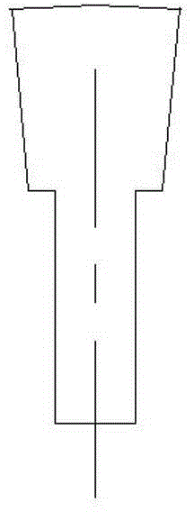
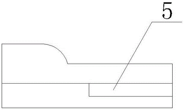
[0022] See Figure 9 and Figure 10 The commutator piece workpiece made by the present invention consists of a sheet body 2 and a step 1 arranged on the top of the sheet body 2. The step 1 and the sheet body 2 are L-shaped, and the left and right sides of the sheet body 2 are provided with a sheet along the height direction of the sheet body. Groove 3, left and right sides 14, inner side 12 of sheet body, left and right sides 13, outer side 11 of the step. The manufacturing method of the commutator segment of the present invention comprises the following steps: a. copper wire rod drawing process, drawing out the section bar that is equivalent to sheet body shape but does not have sheet groove, see figure 1 and figure 2 ; b. Fixed-length cutting process, the profile is cut to the required length, see figure 1 and figure 2 ; c. The first cold heading process, see image 3 , Figure 4 and Figure 11 , in the cavity of the first cold heading die A, the head of the profile...


PUM


Abstract

The invention discloses a commutator segment manufacturing method. The method is characterized by including the steps of a, drawing copper wire materials; b, cutting off at fixed length; c, flatly pre-heading the head of a profile for the first time through first cold heading, and heading a hanging groove in parts below the tops of the left and right sides of a commutator segment body; d, flatly heading the head of the profile for the second time through second cold heading by using the hanging groove as the positioning benchmark, wherein the top of the hanging groove extends upwardly; e, flatly heading the head of the profile for the third time through third cold heading by using the hanging grooves as the positioning benchmark, and forming steps, wherein the forming size of the commutator segment body is slightly larger than the actual size; f, fourth cold heading is used to push a workpiece into a die cavity and allow the workpiece to come out from the discharge outlet in the front side of the bottom of the die cavity by using the hanging groove as the benchmark so as to allow the top of the hanging groove to penetrate the commutator segment body, forming a commutator segment body groove, and using a shaping port formed in the inner wall of the die cavity to shape the commutator segment body and the steps to allow the commutator segment body and the steps reach the actual sizes. The method has the advantages that the commutator segment body of the commutator segment formed by the method is flat and free of warpage and high in forming precision, and the quality of the manufactured commutator is increased.

Description

technical field [0001] The invention relates to a manufacturing method of a commutator segment. Background technique [0002] Commutators are divided into three types: hook-type commutator, slot-type commutator and end-face commutator. The commutator segment of the traditional slot-type commutator is usually composed of a plate body and a step on the top of the plate body. There is an L-shape between the body and the steps. The production of the above-mentioned slot-type commutator segments uses a stamping process, but it will produce a lot of scraps, the utilization rate of copper materials is low, and the production cost is also high. The quality of the type commutator; there is an upsetting process, but because of the need for upper demoulding, the mold cavity must be designed to have a certain taper, which leads to the inclination of the left and right sides of the commutator after cold heading (that is, the upper Thick and thin, which is also a kind of warping and une...

Claims


Application Information

Patent Timeline
IPC IPC(8): B21J5/08B21J5/02B23P15/00H01R43/06
Inventor 金伟陈汶成
Owner ZHEJIANG DONGRUI MACHINERY IND
Learn More