Round tube positioning mechanism and method

A positioning mechanism and positioning method technology, applied in auxiliary devices, auxiliary welding equipment, welding/cutting auxiliary equipment, etc., can solve the problems of high manufacturing cost, low reuse rate, heavy structure and space occupation, and achieve error reduction and universal Robust, easy-to-apply effects

Active Publication Date: 2015-09-02
SHENYANG AIRCRAFT CORP
View PDF8 Cites 15 Cited by
  • Summary
  • Abstract
  • Description
  • Claims
  • Application Information

AI Technical Summary

Problems solved by technology

The traditional positioning method usually uses a professional V-shaped block designed for a fixed size of the outer circle for positioning. This structure is fixed in height and cannot be adjusted. It can only meet the outer circ

Method used


Image

  • Round tube positioning mechanism and method
  • Round tube positioning mechanism and method
  • Round tube positioning mechanism and method

Examples


Embodiment 1

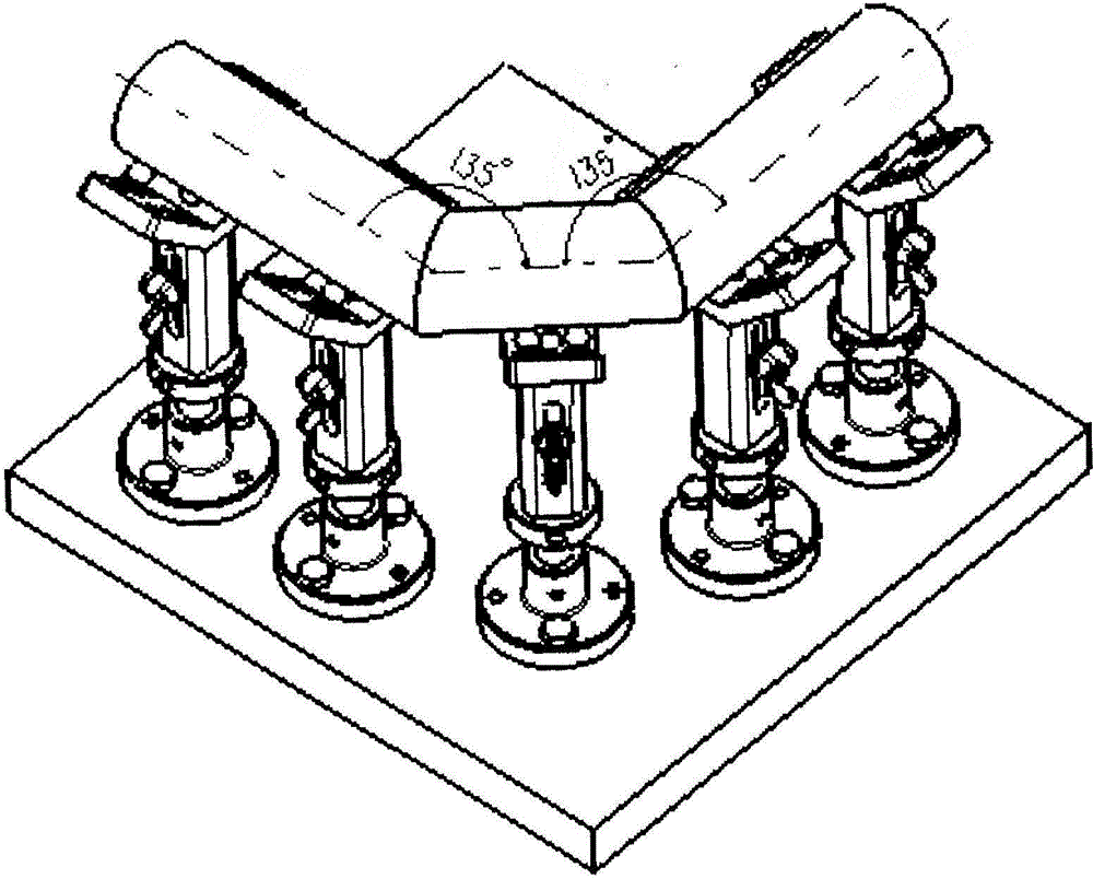
[0025] Such as image 3 As shown, the positioning method of the curved pipe with several circular pipe positioning mechanisms includes the following steps:

[0026] 1) Place the connecting seats 10 of all the circular tube positioning mechanisms on the same horizontal plane, and project the axis of the pipe fittings onto the horizontal plane;

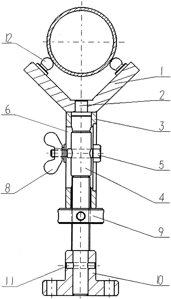
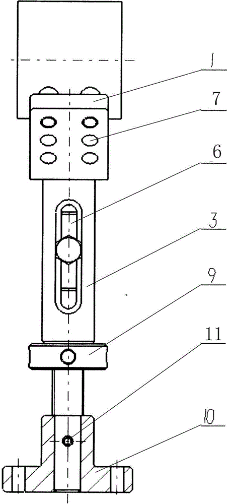
[0027] 2) Select the specifications of the ball bearing 12 according to the size of the cross-sectional diameter of the pipe fitting, and install one on the positioning hole 7 of each supporting surface of the V-shaped support 1, and ensure that the contact point of the ball bearing 12 is in contact with the pipe fitting. The angle between the lines connecting the centers of the cross-sections is greater than or equal to 90°;

[0028] 3) Determine the number of circular tube positioning mechanisms according to the length of the pipe fittings to be supported, and place the circular tube positioning mechanisms sequentially along the proj...

Embodiment 2

[0031] Such as Figure 4 As shown, using several circular tube positioning mechanisms to locate the pipe fittings with height difference on the axis, the fourth step is to use the height gauge to assist in adjusting the height of each circular pipe positioning mechanism, and ensure that each ball head support 12 is in point contact with the pipe to be positioned , and the rest of the steps are the same as in Embodiment 1.

Embodiment 3

[0033] Such as Figure 5 As shown, the positioning method of a short pipe with a circular pipe positioning mechanism includes the following steps:

[0034] 1) Select the specifications of the ball bearing 12 according to the size of the cross-sectional diameter of the pipe fitting, and install two positioning holes 7 on each support surface of the V-shaped support 1, and ensure that the contact point of the ball bearing 12 is in contact with the pipe fitting. The angle between the lines connecting the centers of the cross-sections is greater than or equal to 90°;

[0035] 2) Directly place the short pipe fittings on the four ball bearings 12 for positioning.


PUM


Abstract

The invention relates to a round tube positioning mechanism. The lower part of a sliding supporting rod is positioned in the axis of a connection base through a cylindrical pin; fine threads are arranged in the middle of the sliding supporting rod and are in threaded connection with an adjustment nut; the adjustment nut supports a guide sleeve; symmetrically arranged vertical long-strip stepped holes are formed in the guide sleeve; a through hole is formed in the upper part of the sliding supporting rod; a finished bolt sequentially penetrates through one long-strip stepped hole and the through hole of the sliding supporting rod and then is movably connected with a butterfly nut in the other long-strip stepped hole; the bottom surface of a bolt head of the finished bolt and the bottom surface of the butterfly nut are clamped and connected onto the long-strip stepped holes respectively; a stepped pin is arranged in the axis of the upper end of the guide sleeve; a V-shaped supporting base is arranged on the stepped pin; symmetrical ball bearings are arranged on the V-shaped supporting base. The round tube positioning mechanism is simple to machine, the height can be adjusted, meanwhile, the positioning precision is high, and with the adoption of a positioning method, various specifications of pipe fittings can be positioned and supported.

Description

technical field [0001] The invention relates to a circular pipe positioning mechanism and a positioning method thereof, which are used for positioning support of various pipe fitting products whose outer circle is the positioning reference. Background technique [0002] In the field of welding or mechanical assembly and installation, most circular pipe fittings are welded or assembled with similar positioning and support forms, but the specifications and shapes are different, so a positioning support mechanism is needed to achieve fast and accurate positioning, and can adapt to the specifications of pipe fittings The range and shape are various. The traditional positioning method usually uses a professional V-shaped block designed for a fixed size of the outer circle for positioning. This structure is fixed in height and cannot be adjusted. It can only meet the outer circle positioning of a small size and can only locate the cylindrical surface. The structure It takes up a ...

Claims


Application Information

Patent Timeline
IPC IPC(8): B23K37/053B25B11/02
CPCB23K37/0533B25B11/02
Inventor 张鹏辛久庆孙莹
Owner SHENYANG AIRCRAFT CORP
Why Eureka
Try Eureka