Cantilever beam device used for installing steel box beam

A technology of steel box girder and main girder, which is applied in the erection/assembly of bridges, bridges, bridge construction, etc., can solve the problems of inconvenient disassembly and reuse, low construction efficiency, and troublesome erection, etc., and achieves easy disassembly and reuse without affecting construction. Efficiency and ease of installation

Active Publication Date: 2015-09-02
CHINA MCC5 GROUP CORP
View PDF3 Cites 0 Cited by
  • Summary
  • Abstract
  • Description
  • Claims
  • Application Information

AI Technical Summary

Problems solved by technology

[0005] The invention provides a beam lifting device for installing a steel box girder, which solves the problem that the existing steel box girder needs to set up a temporary support device during the installation process, and the erection is limited by the site, and the erection is troublesome, resulting in low construction efficiency , the cost is high, the technical problem of being inconvenient to disassemble and reuse is achieved, and the cantilever structure in this application is used to facilitate the installation of the steel box girder, and it is not limited by the site, does not affect the construction efficiency, the cost is low, and it is easy to disassemble Technical Effects of Reuse

Method used


Image

  • Cantilever beam device used for installing steel box beam

Examples


Embodiment

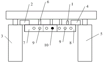
[0021] In the embodiment, a kind of cantilever device for installing steel box girder is provided, please refer to figure 1 , the device includes:

[0022] The main beam, the main beam is placed horizontally, the main beam is provided with a lifting lug 1, one end of the first support beam 2 is connected to the upper surface of the left end of the main beam, and the other end of the first support beam 2 is connected to the upper surface of the left end of the main beam. The first concrete bridge column 3 is connected, one end of the second support beam 4 is connected with the upper surface of the right end of the main beam, and the other end of the second support beam 4 is connected with the second concrete bridge column 5, and the main beam 4 is connected with the second concrete bridge column 5. The beam, the first support beam 2, and the second support beam 4 form a U-shaped beam, and the upper surface of the main beam is provided with N steel columns 6, and the N is a posi...


PUM


Abstract

The invention discloses a cantilever beam device used for installing a steel box beam. The device comprises a main beam which is horizontally placed and provided with a lifting lug, one end of a first supporting beam is connected with the upper surface of the left end of the main beam, the other end of the first supporting beam is connected with a first concrete bridge column, one end of a second supporting beam is connected with the upper surface of the right end of the main beam, the other end of the second supporting beam is connected with a second concrete bridge column, the main beam, the first supporting beam and the second supporting beam form a U-shaped beam, and N steel stand columns are arranged on the upper surface of the main beam. The technical effects that the steel box beam can be installed conveniently, site limitation is avoided, construction efficiency is not affected, cost is low and the cantilever beam device can be conveniently disassembled and reused are achieved through the cantilever beam structure.

Description

technical field [0001] The invention relates to the field of installation of steel box girders, in particular to a beam cantilever device for installing steel box girders. Background technique [0002] Generally, for relatively large steel box girder bridges, due to the limitation of transportation conditions, the steel box girder is divided into several small steel box girder units in the width direction; after the multiple small steel box girders are transported to the site, the site is assembled and welded in the air to make. The concrete columns at the installation site are independent columns without a cover beam structure. During on-site assembly, they need to be installed from the centerline of the bridge, and temporary supports are required to fix them. However, it is troublesome to erect temporary supports due to site restrictions, resulting in low construction efficiency. The cost is high, and it is not convenient to disassemble and reuse. [0003] To sum up, in ...

Claims


Application Information

Patent Timeline
Patent Type & Authority Applications(China)
IPC IPC(8): E01D21/00
Inventor 姜友荣陈方唐丽刘云辉
Owner CHINA MCC5 GROUP CORP
Why Eureka
Try Eureka