
A device for controlling the lifting of a washstand

A washstand and front bracket technology, which is applied in the field of devices for controlling the lift of the washstand, can solve the problems of unsuitable floor-standing washstands, etc., and achieve the effect of easy washing, full of fun, and training the ability of washing

Active Publication Date: 2016-09-28
SHENYANG INSTITUTE OF CHEMICAL TECHNOLOGY
View PDF6 Cites 0 Cited by
  • Summary
  • Abstract
  • Description
  • Claims
  • Application Information

AI Technical Summary

Problems solved by technology

[0004] Although the auxiliary device of the lifting washstand is convenient to use and has a wide range of applications, the auxiliary device of the lifting washstand still has some shortcomings. If it is not suitable for the floor-mounted washstand, it will take a while to take out the battery for charging, etc.

Method used


Image

  • A device for controlling the lifting of a washstand
  • A device for controlling the lifting of a washstand
  • A device for controlling the lifting of a washstand

Examples


Embodiment 1

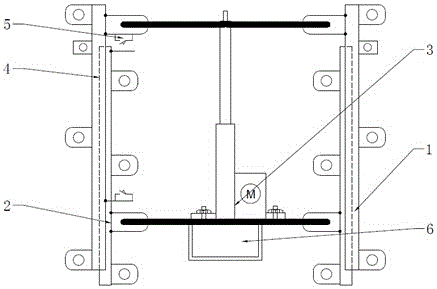
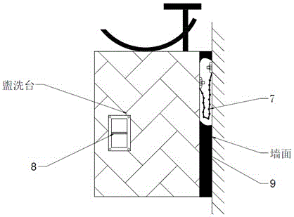
[0026] A controllable lift-type washstand auxiliary device, mainly including a front bracket 1, a rear bracket 2, an electric push rod 3, a steel ball slide rail 4, a travel switch 5, a battery 6, a safety chain 7, a control switch 8, and a plastic outer protective shell 9 and its appendices. Combination in Example 1 figure 1 , fix the front support 1 and rear support 2 of the auxiliary device on the back of the washstand and the wall respectively, fasten them with screws, place the electric push rod 3 on the rear support 2, and reinforce them with bolts; form the switch 5 according to the predetermined After the position is installed, install the battery 6 in the battery area as marked, press Figure 4 Connect the circuit; connect the washstand with the front bracket 1 and the rear bracket 2 through the steel ball slide rail 4, fix the top of the electric push rod 3 and the top of the rear bracket 2 with bolts, and debug the device. After commissioning the auxiliary device,...

Embodiment 2

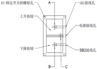
[0029] After the device has been debugged, choose a suitable location to install the control switch 8. The design diagram of the control switch of this device is as follows: Figure 3a , Figure 3b shown. The control switch 8 of the device is two up and down, and the ascending movement of the washstand can be realized when pressing the ascending switch; the descending movement of the washstand can be realized when pressing the descending switch. When the device rises to the limit position, touch the travel switch to make KM3 energized, KM3 normally open electric contact closes and KM3 normally closed electric contact opens, KM1 loses power, the circuit is disconnected, the electric push rod stops working, and the device does not rise again; The same is true when descending to the limit position. The control switch 8 is a humanized rubber outsourcing button. The switch button can be fixed by bolts or glued to any position on the back plane, and has functions such as waterproo...

Embodiment 3

[0031] Embodiment 3 The switch 5 can be directly installed on the rear support 2 in the installation, and the front support 1 can also be equipped with a stopper to control the up and down range of the washstand.


PUM


Abstract

A device for controlling the lifting of a washstand, relating to a bathroom device, the front support (1) and the rear support (2) of the device are connected by a steel ball slide rail (4); the storage battery (6) provides electric energy for the electric push rod (3) Support the up and down movement of the washstand; the limit switch (5) controls the device to drive the upper and lower limit positions of the washstand; the safety chain (7) prevents the heavy pressure of the washstand from breaking the device and causing the washstand to fall off; the control switch (8) can control the device Up and down movement; the plastic outer protective shell (9) is fixed on the two ends of the washstand, so that the auxiliary device has a beautiful appearance and prevents fingers, hair, etc. from entering the device. The invention provides a method for using the auxiliary device. The auxiliary device for washstands proposed by the invention has low cost, low energy consumption, simple installation and easy use, can improve children's discovery thinking, and is convenient for the elderly, children and some disabled people. It can be widely used in non-floor washstands such as homes, companies, and public facilities, replacing traditional non-adjustable washstands, and is convenient for people to use washstands in daily life.

Description

technical field [0001] The invention relates to a sanitary device, in particular to a device for controlling the lifting of a washstand. Background technique [0002] The height of washstands in modern life is all aimed at the height of adults, and the area of ​​the bathroom is limited, so it is impossible to install two washstands with different heights at the same time. Therefore, for this kind of phenomenon, for vulnerable groups such as the elderly and children, it causes great inconvenience in life. There are many kinds of common washstands, and for families whose washstands have been fully decorated, it is desired to make the existing washstands move up and down through control. Therefore, an auxiliary device that can control the lifting of the washstand is invented, which can make the washstand move up and down. That is, the needs of life are facilitated, and the waste of resources is also reduced. [0003] The structure of this auxiliary device includes a front br...

Claims


Application Information

Patent Timeline
Patent Type & Authority Patents(China)
IPC IPC(8): E03C1/324
Inventor 郭北涛张众宇
Owner SHENYANG INSTITUTE OF CHEMICAL TECHNOLOGY
Learn More