Drilling waste collection and lifting device for drilling

A technology for transferring devices and waste, applied in the direction of earthwork drilling, wellbore/well parts, etc., which can solve the problems of uncontinuous operation, easy damage of motor, easy adhesion of drilling cuttings, etc., and achieves compact structure, convenient use, and avoids Effect of cuttings adhesion

Active Publication Date: 2017-09-05
克拉玛依金鑫油田环保工程有限公司
View PDF8 Cites 1 Cited by
  • Summary
  • Abstract
  • Description
  • Claims
  • Application Information

AI Technical Summary

Problems solved by technology

[0004] The present invention provides a device for collecting and transferring waste while drilling, which overcomes the above-mentioned deficiencies in the prior art and can effectively solve the problem of collecting cuttings in the existing The drill cuttings in the device are easy to adhere to the collecting tank, or / and accumulate at a certain point during the propulsion process, which will cause the motor to be easily damaged, unable to work continuously, low working efficiency, and inconvenient cleaning

Method used


Image

  • Drilling waste collection and lifting device for drilling
  • Drilling waste collection and lifting device for drilling

Examples


Embodiment Construction

[0024] The present invention is not limited by the following examples, and specific implementation methods can be determined according to the technical solutions of the present invention and actual conditions.

[0025] In the present invention, for the convenience of description, the description of the relative positional relationship of each component is described according to the layout of Figure 1 of the specification, such as: the positional relationship of front, rear, top, bottom, left, right, etc. It is determined according to the layout direction of the drawings in the description.

[0026] Below in conjunction with embodiment and accompanying drawing, the present invention will be further described:

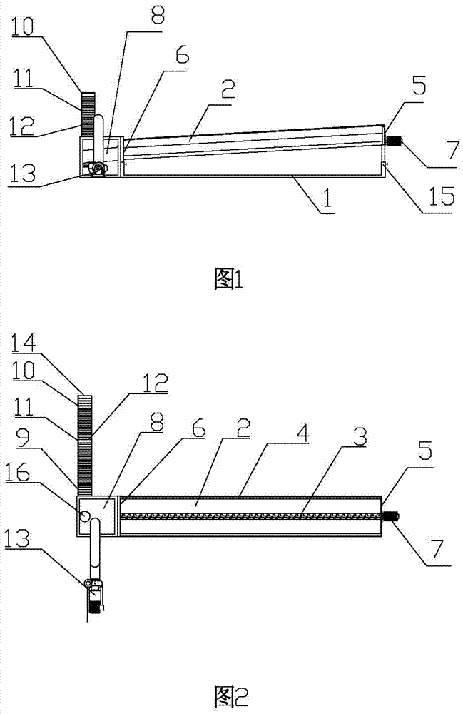
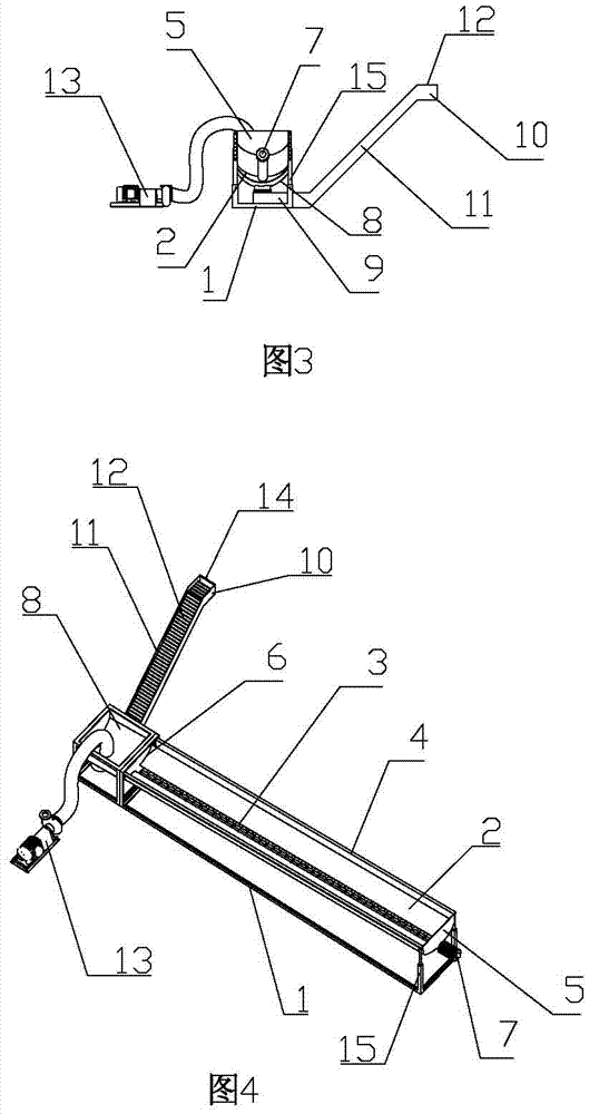
[0027] As shown in accompanying drawings 1, 2, 3, and 4, the lifting and transferring device for collecting waste while drilling includes a collection component and a lifting and transferring component. The propeller 3 and the collection and cleaning pipe 4, the bottom ...


PUM


Abstract

The invention relates to the technical field of cuttings collection, and is a lifting and transferring device for collecting waste while drilling, which includes a collecting component and a lifting and transferring component. The bottom of the collection tank is seated on the base of the bracket. The projection on the right side of the collection tank is a concave shape with an upward opening and a large top and a small bottom. The right end of the collection tank is fixed with an anti-overflow baffle to prevent material from overflowing. The left end of the collection tank is the outlet for collecting materials. , A screw propeller that can push the material from right to left is installed on the inner side of the lower part of the collecting tank. The structure of the present invention is beneficial to site cleaning by adding a collection and cleaning pipe at the collection tank, and the equipment runs stably. When the phenomenon of drill cuttings sticking to the collection tank occurs, the cleaning water source and the collection and cleaning pipe can be connected through the connection joint. Together, the fluidity of the cuttings can be enhanced, thereby effectively avoiding the adhesion of the cuttings.

Description

technical field [0001] The invention relates to the technical field of cuttings collection, and relates to a device for collecting, lifting and transferring waste while drilling for drilling. Background technique [0002] After the promulgation of the new "Environmental Protection Law" on January 1, 2015, all domestic oil fields require that drilling cuttings in environmentally sensitive areas must be controlled without landing, and it is not allowed to spill the ground or dig mud pools. Currently, forklifts and small cuttings collection tanks are mainly used in China. , Excavators, solidification tanks and other equipment are used to process mud and cuttings while drilling, which can meet the collection and treatment of mud and cuttings at different stages of drilling, and meet the requirements of on-site mud non-falling treatment. But there are the following deficiencies: (1) Excavators, forklifts, etc. need a large operating space, and it is difficult for a standard well ...

Claims


Application Information

Patent Timeline
Patent Type & Authority Patents(China)
IPC IPC(8): E21B41/00
Inventor 王茂仁冯建建魏宏姚永清
Owner 克拉玛依金鑫油田环保工程有限公司
Why Eureka
Try Eureka