
Synchropoint identification method and system of synchronizer

An identification method and synchronizer technology, which can be applied to components with teeth, belts/chains/gears, mechanical equipment, etc., can solve the problem of inability to accurately obtain the position of the synchronizer, and achieve the effect of reducing impact

Active Publication Date: 2015-09-02
SHANGHAI AUTOMOBILE GEAR WORKS +1
View PDF10 Cites 11 Cited by
  • Summary
  • Abstract
  • Description
  • Claims
  • Application Information

AI Technical Summary

Problems solved by technology

However, this technology cannot accurately obtain the real position of the synchronizer when the synchronizer fork is deformed

Method used


Image

  • Synchropoint identification method and system of synchronizer
  • Synchropoint identification method and system of synchronizer

Examples


Embodiment 1

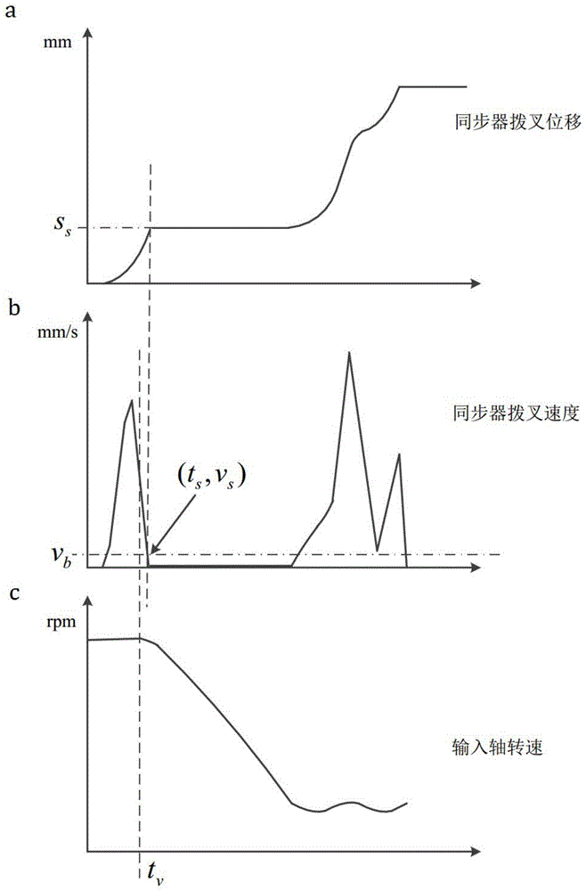
[0029] This embodiment proposes a method for identifying the synchronization point of the synchronizer. The method identifies the position of the synchronization point of the synchronizer according to the speed of the synchronizer fork and the rotational speed of the input shaft.

[0030] In this embodiment, the dual-clutch transmission is taken as an example, and the specific implementation steps are as follows:

[0031] 1) After the transmission control core issues a shift synchronization command, it starts to detect the displacement of the synchronizer fork;

[0032] 2) After the transmission control core issues a shift synchronization command, it starts to detect the input shaft speed;

[0033] 3) Calculate the axial velocity of the synchronizer fork according to the displacement of the synchronizer fork, and the calculation method is the difference method;

[0034] 4) When the detected rotational speed of the input shaft changes, record this moment as t v ;

[0035] 5)...


PUM


Abstract

Disclosed is a synchropoint identification method of an automatic double-clutch gear. The synchropoint identification method includes tracking revolving speed of an input shaft and axial speed of a synchronizer fork in real time at the beginning of gear shift synchronizing, tracking the axial speed of the synchronizer fork when the variation of the revolving speed of the input shaft exceeds the threshold, and using the displacement of the synchronizer fork as the updated synchropoint when the variation of the revolving speed is lower than the axial speed threshold. The speed of the synchronizer fork can be used as principal judgment condition and the revolving speed of the input shaft can be used as auxiliary judgment condition, so that impact and collision when a synchronizer coupling and a synchronous ring are locked in place can be avoided, noise and wear can be reduced, service life of synchronizer parts is prolonged, accurate information of synchropoints can be provided for control of a synchronous controller, and control accuracy and performance are improved.

Description

technical field [0001] The present invention relates to a technology in the field of automobile transmission, in particular to a method and system for identifying a synchronizer synchronization point of a dual-clutch automatic transmission or a similar mechanical automatic transmission. Background technique [0002] The dual-clutch automatic transmission realizes the action of the synchronizer through the transmission control unit and the executive mechanism, replacing the original shift synchronization operation realized by the driver. Due to the tolerances in the machining of the parts and the inevitable wear of the parts after long-term work, the synchronization point of the synchronizer changes, making the controller unable to obtain an accurate synchronization point and the transmission control core unable to give accurate control commands , so that the shift synchronization force will be loaded in advance. This process will cause a violent collision between the tooth e...

Claims


Application Information

Patent Timeline
IPC IPC(8): F16H61/04F16H63/30
CPCF16H61/0403F16H63/30F16H2710/00
Inventor 鲁统利张建武李鸿魁李育黄明礼丁健
Owner SHANGHAI AUTOMOBILE GEAR WORKS
Learn More