Nondestructive testing method and device for crack of metal part

A non-destructive testing and component technology, applied in material defect testing and other directions, can solve problems such as high temperature rise, and achieve the effect of simple processing time, short processing time, and easy analysis

Inactive Publication Date: 2015-09-02
DALIAN UNIV OF TECH
View PDF7 Cites 9 Cited by
  • Summary
  • Abstract
  • Description
  • Claims
  • Application Information

AI Technical Summary

Problems solved by technology

At the same time, due to the effect of Joule heat, more heat is generated at the crack tip and a higher temperature rise compared to other parts of the component

Method used


Image

  • Nondestructive testing method and device for crack of metal part
  • Nondestructive testing method and device for crack of metal part
  • Nondestructive testing method and device for crack of metal part

Examples


Embodiment Construction

[0016] The present invention will be described in detail below in conjunction with the accompanying drawings and embodiments.

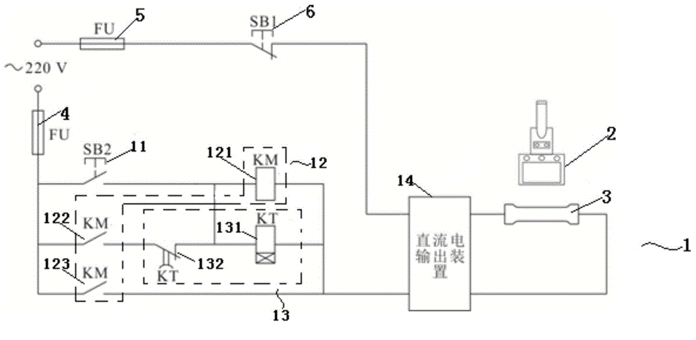
[0017] Such as figure 2 As shown, the device of the present invention includes a time-controllable DC output circuit 1 and an infrared thermal imager 2 .

[0018] The time-controllable direct current output circuit 1 includes a move-on button 11 , a contactor 12 , a time relay 13 and a direct current output device 14 .

[0019] The closing button 11 is used to control the opening of the time-controllable direct current output circuit 1 .

[0020] The contactor 12 is used to control the on-off of the DC output circuit 1 with a controllable time, and includes a contactor coil 121 , a first contactor moving contact 122 and a second contactor moving contact 123 .

[0021] The time relay 13 is used to control the time-delayed disconnection of the DC output circuit 1 , which includes a time relay coil 131 and a time relay break contact 132 .

[0022] Th...


PUM


Abstract

The invention relates to a nondestructive testing method and a nondestructive testing device for a crack of a metal part. The nondestructive testing method for the crack of the metal part comprises the following steps of (1), connecting the two ends of a to-be-tested part with a direct-current power supply, and enabling an infrared lens of an infrared thermal imager to face the to-be-tested part; (2), selecting the time and the size that the to-be-tested part is subjected to the direct-current power according to the dimension and the material property of the to-be-tested part and a position where the crack damage exists, and electrifying the to-be-tested part; (3), after the electrification of the to-be-tested part is completed, observing and imaging the electrified to-be-tested part through the infrared thermal imager, showing that the crack does not exist in the to-be-tested part if an imaged image is in a same color, and showing that the crack exists in the to-be-tested part if the imaged image is in different colors. As a circumferential motion effect and a Joule heating effect are adopted for the nondestructive testing method and the nondestructive testing device for the crack of the metal part, higher temperature rises can be automatically generated at the position of a crack tip by both the circumferential motion effect and the Joule heating effect, and the position of the crack damage of the part is easily and accurately determined. In view of reasons above, the nondestructive testing method and the nondestructive testing device for the crack of the metal part can be widely used for the field of the nondestructive testing of metal cracks.

Description

technical field [0001] The invention relates to a method and device for non-destructive detection of cracks, in particular to a method and device for non-destructive detection of surface and shallow cracks of metal parts. Background technique [0002] As a common form of component failure, metal cracks will rapidly reduce the strength and reliability of components. In order to ensure the safe operation of equipment, it is necessary to judge the damage of parts in time and take corresponding repair measures. In addition, for damaged parts that have been repaired, a reasonable mechanism is also required to judge the repair effect. Because of its non-destructiveness and reliability, the non-destructive detection method of cracks has a wide application value in aviation industry, aerospace industry, military industry and civil industry. [0003] The non-destructive testing methods that have been applied at present mainly include magnetic particle testing, penetrant testing, ed...

Claims


Application Information

Patent Timeline
Patent Type & Authority Applications(China)
IPC IPC(8): G01N25/72
Inventor 邓德伟于涛郝胜智吴东江张永康张洪潮
Owner DALIAN UNIV OF TECH
Why Eureka
Try Eureka