
System and method for quick recognizing fault current in power system

A fault current and power system technology, applied in the direction of measuring electricity, measuring electrical variables, measuring devices, etc., can solve the problems of system complexity, limitations, and inability to know the exact magnitude of the fault.

Inactive Publication Date: 2015-09-02
STATE GRID CORP OF CHINA +2
View PDF9 Cites 2 Cited by
  • Summary
  • Abstract
  • Description
  • Claims
  • Application Information

AI Technical Summary

Problems solved by technology

The traditional short-circuit fault identification method needs to use Fourier transform to extract the fundamental wave component, which is slow to identify and often takes more than 20ms
However, using a pure hardware circuit, using the two criteria of current i and current change rate di / dt, and using logic operations to identify whether the fault current exceeds the preset threshold to identify the fault current, although this method can achieve fast identification However, this method can only know whether the fault current exceeds the threshold, but cannot know the exact magnitude of the fault, so it is limited in practical application
In addition, using hardware or numerical calculations to obtain the first and second derivatives of the current to calculate the peak value of the periodic component of the short-circuit current, although the effect of rapid quantitative identification can be achieved, the hardware and software costs are relatively large, and the system is relatively complex

Method used


Image

  • System and method for quick recognizing fault current in power system
  • System and method for quick recognizing fault current in power system
  • System and method for quick recognizing fault current in power system

Examples


Embodiment Construction

[0041] The present invention will be described in further detail below in conjunction with the accompanying drawings.

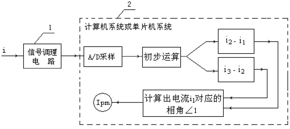
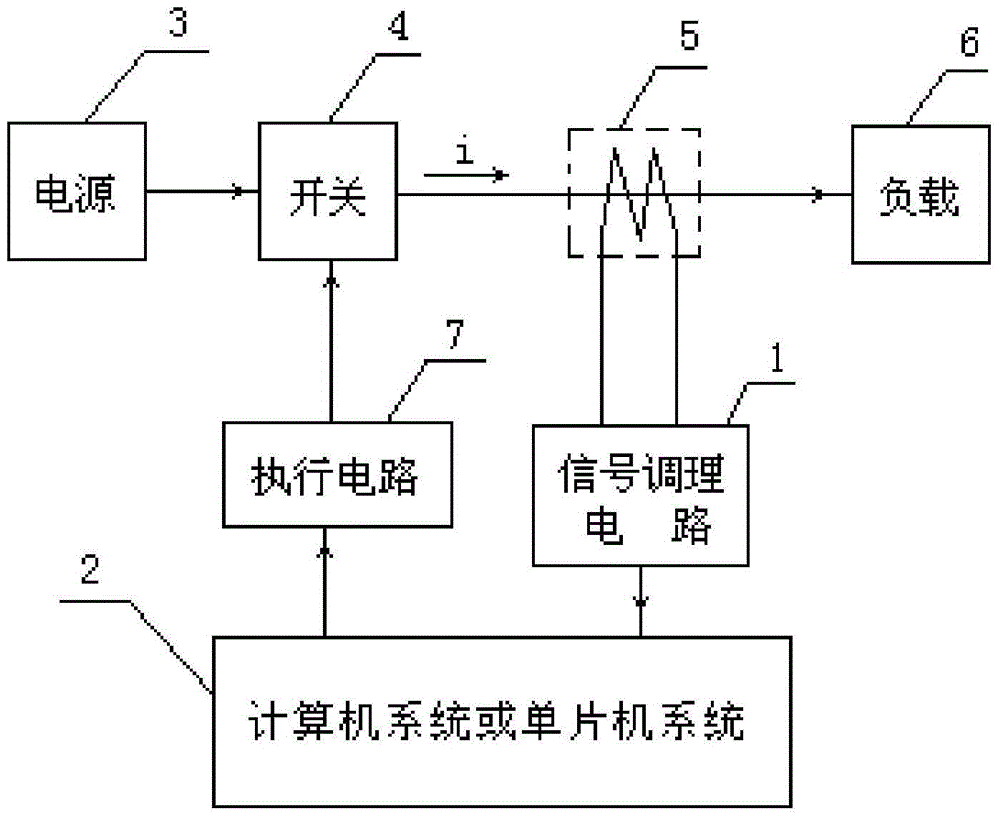
[0042] see figure 1 , 2, The power system fault current rapid identification system of the present invention includes a signal conditioning circuit 1 and a signal processing device 2 . The signal conditioning circuit 1 is used for preprocessing, such as transforming, buffering, amplifying, and filtering the input current i signal; the signal processing device 2 is a computer system or a single-chip microcomputer system, and the single-chip microcomputer system is an MCU, DSP or FPGA module, which is used for conditioning. The current signal is sampled at equal time intervals, and the peak value I of the current periodic component is obtained through the operation of the sampled values pm .

[0043] The fast identification method of the power system fault current of the present invention continuously samples the input current signal at equal time intervals Δ...


PUM


Abstract

Disclosed is a system and method for quick recognizing fault current in a power system. The system for quick recognizing fault current in the power system includes a power supply connected to a load via a switch. A current sensor is arranged on an incoming line of the load. The current sensor transfers a detected current signal, which is subjected to pre-treatment of a signal regulating circuit, to a signal processing device for numerical value sampling. A peak value of a current periodic component is obtained through a sampled numerical value. The signal processing device compares the peak value with a pre-set value, and controls the switch according to the comparative result. The method comprises: continuously performing sampling of an input current signal in an equal time interval through the signal processing device to obtain a current discrete value sequence; selecting a plurality of sampled values in fixed time interval from the sequence; performing mathematical calculation of difference value and trigonometric function of the selected values to obtain the peak value of the current periodic component; comparing the peak value with the pre-set value; and if the detected peak value is larger than the pre-set value, controlling the switch to be off. According to the invention, the fault current can be quickly recognized, and the cost is saved.

Description

technical field [0001] The invention relates to the field of power system current detection, in particular to a system and method for quickly identifying fault currents in a power system. Background technique [0002] When a short-circuit fault occurs in the power system or the power system of an industrial user, in order to minimize the adverse effects caused by the short circuit, it is required that the relay protection or other auxiliary electronic devices can identify the short-circuit fault at the fastest speed and accurately predict the level of the short-circuit current , and control the action of the circuit breaker or other breaking devices according to a certain strategy at the first time to cut off the fault circuit. The traditional short-circuit fault identification method needs to use Fourier transform to extract the fundamental wave component, which is slow to identify and often takes more than 20ms. However, using a pure hardware circuit, using the two criter...

Claims


Application Information

Patent Timeline
IPC IPC(8): G01R31/02
Inventor 罗万兴李品德贺鸿祺宋义扫智礼
Owner STATE GRID CORP OF CHINA
Learn More