
Unmanned vehicle-side longitudinal coupling tracking control method based on rapid terminal sliding mode principle

A terminal sliding mode and tracking control technology, which is applied in two-dimensional position/channel control, adaptive control, general control system, etc., can solve the problems of less research, large tracking error, and low control accuracy

Active Publication Date: 2015-09-02
枣庄市新时代网络工程有限公司
View PDF3 Cites 29 Cited by
  • Summary
  • Abstract
  • Description
  • Claims
  • Application Information

AI Technical Summary

Problems solved by technology

On the other hand, when the vehicle performs some complex planned maneuvers such as changing lanes and turning at intersections in an environment with moving obstacles, it is required to track the planned position sequence and planned velocity sequence at the same time. At this time, there is a strong coupling, if the side-to-longitudinal decoupling control algorithm is still used, a large tracking error will be generated
[0004] Some researchers have conducted research on side-longitudinal coupling control strategies based on the coupling effect of vehicle side-longitudinal motion, but the current coupling control strategy of side-longitudinal motion is mainly aimed at vehicle platoon control, for the control of high mobility behavior of a single autonomous vehicle, such as Vehicles perform some complex planning maneuvers such as changing lanes and turning at intersections in an environment with moving obstacles, with little research or low control accuracy

Method used


Image

  • Unmanned vehicle-side longitudinal coupling tracking control method based on rapid terminal sliding mode principle
  • Unmanned vehicle-side longitudinal coupling tracking control method based on rapid terminal sliding mode principle
  • Unmanned vehicle-side longitudinal coupling tracking control method based on rapid terminal sliding mode principle

Examples


Embodiment Construction

[0056] According to the principle of side-to-longitudinal coupling control, this design is further described in detail.

[0057] see figure 1 , the invention is used for the design of the tracking controller when the unmanned vehicle tracks the planned trajectory.

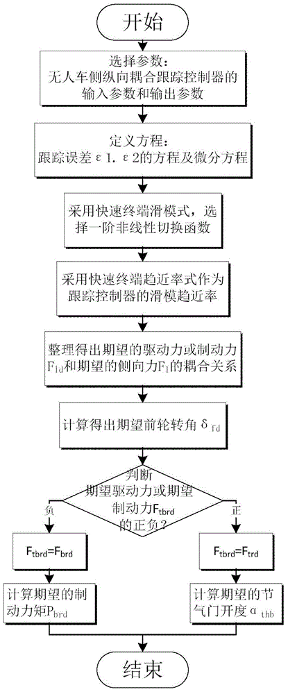
[0058] see figure 2 , the present invention is based on the rapid terminal sliding mode principle of unmanned vehicle side longitudinal coupling tracking control method is divided into the following nine steps, each step is as follows:

[0059] 1) Select the input parameters and output parameters of the unmanned vehicle side longitudinal coupling tracking controller according to the planned trajectory:

[0060] (1a) Input parameters: the current coordinates of the center of mass of the unmanned vehicle and the coordinate error of the planned point on the planned trajectory X-X d , Y-Y d ; The error between the yaw angle of the speed vector of the unmanned vehicle and the yaw angle of the planning point where...


PUM


Abstract

The invention provides an unmanned vehicle-side longitudinal coupling tracking control method based on a rapid terminal sliding mode principle. The method comprises the following steps: 1) selecting an input parameter and an output parameter of an unmanned vehicle-side longitudinal coupling tracking controller; 2) defining a tracking control error and a state equation; 3) using the tracking control error as a state variable and establishing a rapid terminal sliding mode; 4) taking a rapid terminal tendency rate as a sliding mode tendency rate of the tracking control; 5) according to a vehicle dynamics model and the above content, deriving a coupling relation between an expected driving force or a braking force and an expected side force; 6) calculating an expected front-wheel turning angle; 7) according to positive or negative of obtained reverse longitudinal force model output, determining whether an expected throttle percentage or an expected braking torque should be calculated currently; 8) calculating the expected throttle percentage or the braking torque. From a simulation result, by using the method in the invention, error precision of position tracking control is increased and good error precision of speed tracking control is possessed.

Description

【Technical field】 [0001] The invention relates to the technical field of autonomous driving and sliding mode control of an unmanned vehicle, in particular to a tracking control method for realizing side longitudinal coupling of an unmanned vehicle. 【Background technique】 [0002] The motion control of unmanned vehicles is the key technology of the manipulation control layer in the navigation control architecture, and the motion control algorithm is the core research content of this layer. The motion control here is the tracking control based on the planned trajectory. Tracking control of autonomous vehicles includes longitudinal tracking control and lateral tracking control. Longitudinal tracking control is to control the driving speed of the vehicle to be consistent with the planned speed, and to maintain a certain driving distance with the vehicle in front. Lateral tracking control is to control the driving direction of the vehicle so that it can travel along the planned ...

Claims


Application Information

Patent Timeline
IPC IPC(8): G05D1/02G05B13/04
Inventor 杨静荣海军陈鹏鹏杜少毅薛建儒
Owner 枣庄市新时代网络工程有限公司
Learn More