Method for detecting surface film of intelligent information equipment
A technology for information equipment and detection methods, applied in the input/output process of data processing, instruments, electrical digital data processing, etc. Utilization, convenient use effect
- Summary
- Abstract
- Description
- Claims
- Application Information
AI Technical Summary
Problems solved by technology
Method used
Image
Examples
Embodiment 1
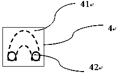
[0017] In this embodiment, a touch unit for a touch screen is provided, such as figure 1 As shown, the touch unit includes a conductive layer 4, and the conductive layer 4 includes a logo coverage area (ie icon area 42) and a touch extension area (ie touch area 41) connected to each other. The touch extension area It is also called the touch area 41 , and the logo coverage area is also called the icon area 42 . The logo coverage area (i.e. icon area 42) covers the touch identification on the touch screen, and the touch extension area (i.e. touch area 41) extends to the blank space of the touch screen or outside the touch screen , by touching the touch extension area (i.e. the touch area 41), the operation of the touch identification covered by the identification coverage area (i.e. the icon area 42) can be realized. In particular, the conductive layer 4 is like an inverted U-shaped, the top of the inverted U-like shape corresponds to the touch extension area (ie, the touch ar...
Embodiment 2
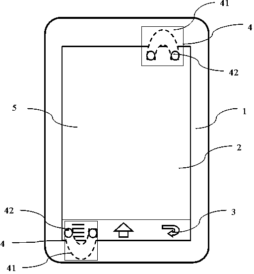
[0025] A touch screen is provided in this embodiment, such as figure 2 As shown, one or more touch units are arranged on the touch screen. The touch unit includes a conductive layer 4, and the conductive layer 4 includes a logo coverage area (ie icon area 42) and a touch extension area (ie touch area 41) connected to each other. The touch extension area is also called The touch area 41 and the identification coverage area are also referred to as the icon area 42 . The logo coverage area (i.e. icon area 42) covers the touch identification on the touch screen, and the touch extension area (i.e. touch area 41) extends to the blank space of the touch screen or outside the touch screen , by touching the touch extension area, the touch sign covered by the sign coverage area can be operated.
[0026] The touch extension area (touch area 41 ) of the touch unit is set in a blank area in the touch screen, or can be set outside the touch screen. If the touch area is set in the touch ...
Embodiment 3
[0034] In this embodiment, a film is provided, and the film includes a film base layer covering a touch screen, and one or more touch units are arranged on the film base layer. The touch unit includes a conductive layer 4, and the conductive layer 4 includes a logo coverage area (ie icon area 42) and a touch extension area (touch area 41) connected to each other. The touch extension area is also called touch Control area 41, the identification coverage area is also called icon area 42. The logo coverage area (ie icon area 42 ) covers the touch logo on the touch screen, and the touch extension area (touch area 41 ) extends to the blank space of the touch screen or outside the touch screen, By touching the touch extension area (the touch area 41 ), the touch sign covered by the sign coverage area (ie, the icon area 42 ) can be operated.
[0035] Similarly, the conductive layer 4 is in an inverted U-like shape, the top of the inverted U-like shape corresponds to the touch extens...
PUM
 Abstract
Description
Claims
Application Information
 - R&D
- Intellectual Property
- Life Sciences
- Materials
- Tech Scout
- Unparalleled Data Quality
- Higher Quality Content
- 60% Fewer Hallucinations
Browse by: Latest US Patents, China's latest patents, Technical Efficacy Thesaurus, Application Domain, Technology Topic, Popular Technical Reports.
© 2025 PatSnap. All rights reserved.Legal|Privacy policy|Modern Slavery Act Transparency Statement|Sitemap|About US| Contact US: help@patsnap.com


