Check patentability & draft patents in minutes with Patsnap Eureka AI!

heat flow sensor

A heat flow sensor and source sensor technology, applied in calorimeters, instruments, scientific instruments, etc., can solve the problem of high thermal intrusion of sensors

Active Publication Date: 2018-04-06
GREENTEG
View PDF6 Cites 0 Cited by
  • Summary
  • Abstract
  • Description
  • Claims
  • Application Information

AI Technical Summary

Problems solved by technology

Such a total of three thin polymer films results in a high thermal intrusion of the sensor, even if the sensor is very thin

Method used


Image

  • heat flow sensor
  • heat flow sensor
  • heat flow sensor

Examples


Embodiment Construction

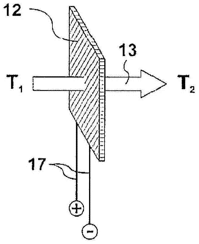
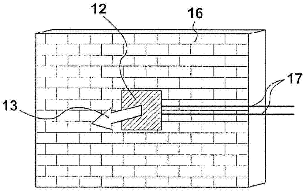
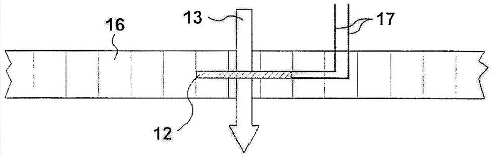
[0025] A schematic view of the WFS is at Figure 1a shown in . The heat flow sensor 12 is passed through by a heat flow 13 . A heat flow 13 flows from the hot side with temperature T1 to the cold side with temperature T2. The voltage induced in the WFS 12 due to the heat flow 13 is measured on the conductive cable 17 . The use of this sensor in Figure 1b with Figure 1c shown in . exist Figure 1b Install the WFS on a measurement object (eg a wall) in . The heat flow 13 flowing through the wall and also through the WFS 12 is measured by a voltage measuring instrument (voltmeter) on the conductive wire 17 by the voltage applied across the WFS. exist Figure 1c , the WFS 12 is embedded in a measurement object (eg, a wall) 16 and is surrounded by the measurement object. The heat flow 13 flowing through the wall and also through the WFS 12 is measured by a voltage measuring instrument (voltmeter) on the conductive wire 17 by the voltage applied across the WFS. The WFS in...


PUM

PropertyMeasurementUnit
thicknessaaaaaaaaaa
thicknessaaaaaaaaaa
thicknessaaaaaaaaaa

Abstract

The present invention relates to a heat flow sensor (WFS) which should be as least invasive as possible and still be robust enough to meet the requirements of various applications, and its application. Here, the heat flow sensor comprises an active sensor element, which is provided on the cold side and on the hot side with heat-conducting elements (8, 9) with high thermal conductivity, wherein the sensor element (1) is covered by an extremely thin, An electrically insulating, chemically inert and highly adhesive protective layer (6) covers or is surrounded by said protective layer.

Description

technical field [0001] The present invention relates to a heat flow sensor (WFS) and its application. Background technique [0002] The heat flow sensor measures the thermal energy (thermal power, heat flow) flowing from the hotter side to the cooler side in each time unit. In application, the flat WFS is mounted on the target, or integrated into the target as needed. There are integration and application examples eg in VAN DER GRAAF. Heat flow (volume) is measured by generating a voltage that depends on the magnitude of the heat flow across the face of the sensor. WFS is known and already used industrially, eg under the names Hukseflux, Sequoia, Captec etc. (Bezeichnung, brand name). [0003] Furthermore, heat flow sensors are used in building engineering technology to measure the thermal insulation properties of walls, or in calorimetry to measure the energy of chemical reactions or to measure the energy of electromagnetic radiation. [0004] Heat flow sensors accordin...

Claims


Application Information

Patent Timeline
Patent Type & Authority Patents(China)
IPC IPC(8): G01J5/10G01K17/20G01K17/00
CPCG01K17/20
Inventor L·杜勒尔T·赫博翎E·施威特尔W·格拉茨P·施泰因
Owner GREENTEG
Features
  • R&D
  • Intellectual Property
  • Life Sciences
  • Materials
  • Tech Scout
  • Unparalleled Data Quality
  • Higher Quality Content
  • 60% Fewer Hallucinations
Learn More