Method, network and system for protection switching

A technology of protection switching and automatic protection switching, which is applied in the field of communication, can solve problems such as inability to complete protection switching and service protection, and achieve the effect of realizing protection switching and enhancing robustness

Active Publication Date: 2018-02-02
HUAWEI TECH CO LTD
View PDF2 Cites 0 Cited by
  • Summary
  • Abstract
  • Description
  • Claims
  • Application Information

AI Technical Summary

Problems solved by technology

For node A, it can detect the link failure, so the service will be switched to the link of A and C (that is, the transport entity 1). However, for B, D and F, because the links between them are normal, If the corresponding fault detection cannot detect the fault, the corresponding switching of these nodes does not occur, so the corresponding protection switching cannot be completed, and service protection cannot be realized

Method used


Image

  • Method, network and system for protection switching
  • Method, network and system for protection switching
  • Method, network and system for protection switching

Examples


Embodiment 1

[0057] Embodiment one: if Figure 4 As shown, the embodiment of the present invention provides a network node. The network node includes: a processing module, configured to determine that only the first transmission entity connected to the network node exists in the second protection domain when it is detected that the first transmission entity connected to the network node in the first protection domain changes from the standby state to the active state. The protection transport entity connected to the border node does not exist in the working transport entity connected to the first border node; the service is switched to the first protection transport entity, wherein the first protection transport entity is the second Protecting the transport entity connected to the network node in the domain; and generating a first automatic protection switching APS message carrying a request triggered by inter-domain protection switching; a sending module, configured to send the first APS ...

Embodiment 2

[0080] Embodiment two: if Image 6 As shown, this embodiment provides yet another network node, the network node is both a border node of the first protection domain and a border node of the second protection domain, and the network node includes: a receiving module, configured to receive information from the second protection domain The protection domain carries the first automatic protection switching APS message of the request to notify the failure of the adjacent protection domain, and the first APS message also carries the identification of the second border node; the processing module is configured to identify the After the second border node is a peer node of the network node, protection switching is performed in the first protection domain, wherein the peer node of the network node refers to a border node and a peer node of the first protection domain at the same time The node of the border node of the second protection domain.

[0081] This network node can be applie...

Embodiment 3

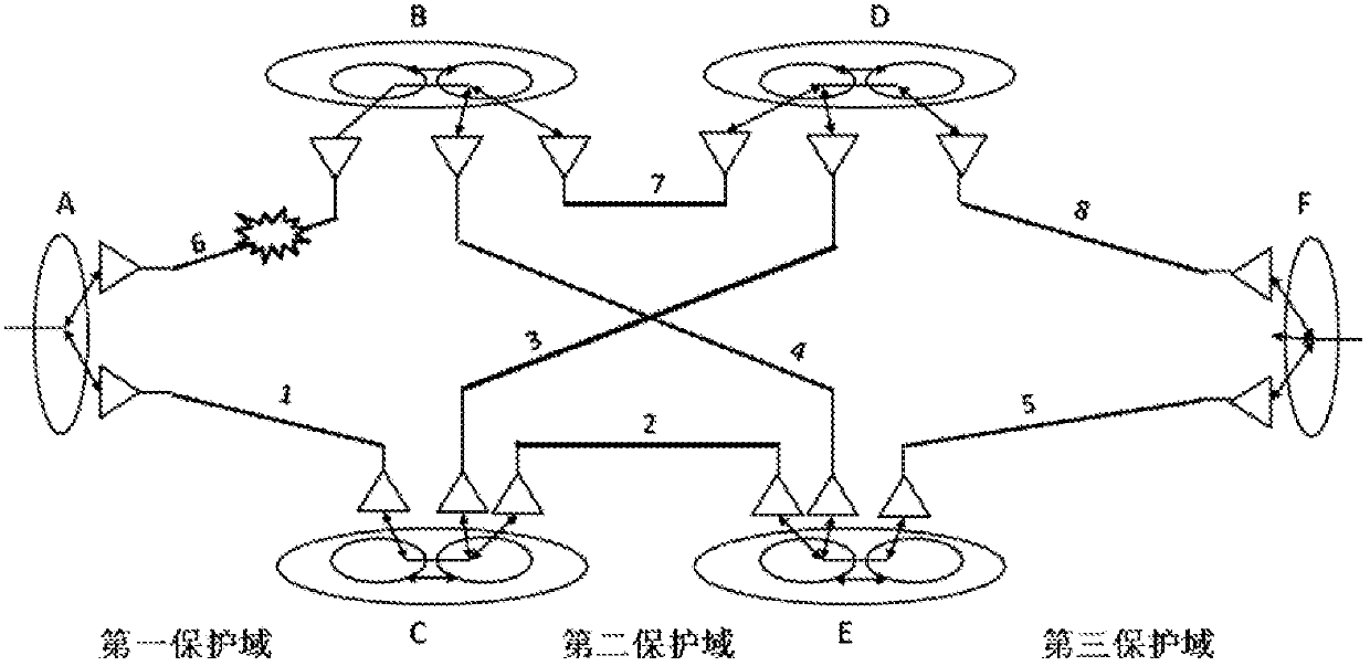
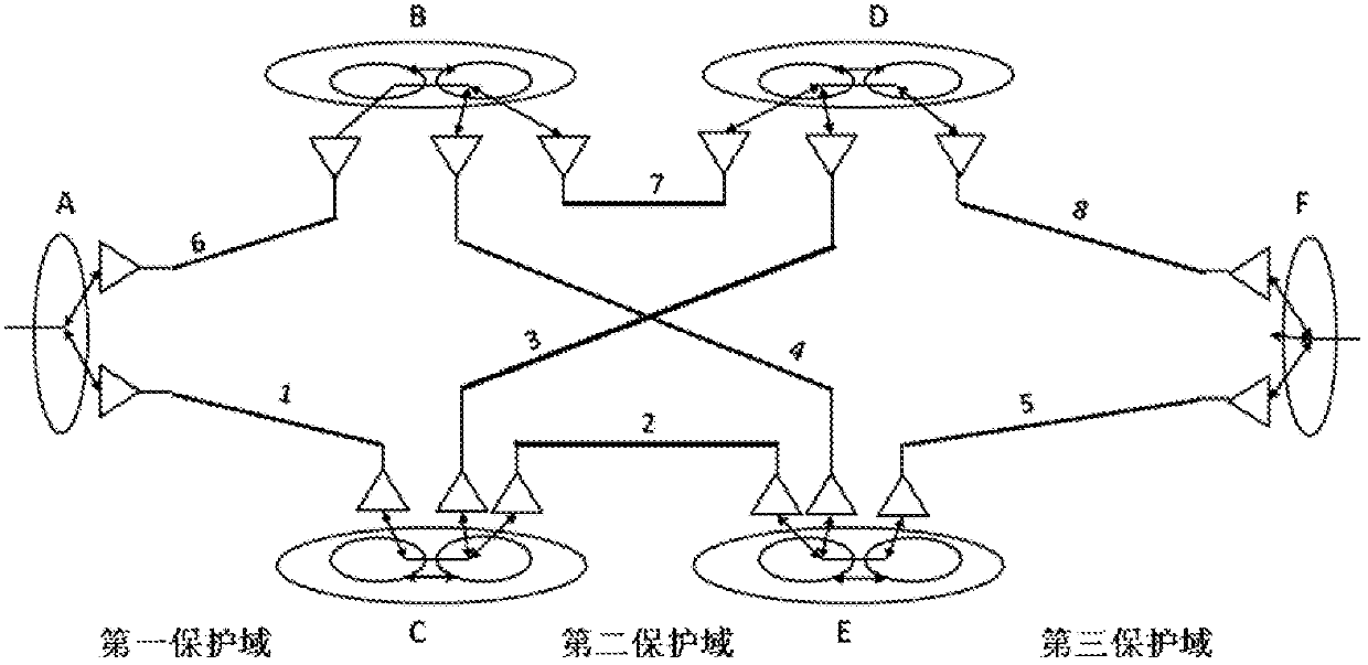
[0092] Embodiment three: as Figure 8 As shown, the embodiment of the present invention provides a protection switching method, which can use the network node provided in Embodiment 1, and can be applied to such as figure 2 In the network structure shown in.

[0093] The method includes: when the first transport entity connected to the first border node in the first protection domain changes from the standby state to the active state, the first border node determines that only the first border node exists in the second protection domain The connected protection transport entity does not exist in the working transport entity connected to the first border node, wherein the first border node is simultaneously a border node of the first protection domain and a border node of the second protection domain; The first border node switches services to a first protection transport entity, and the first protection transport entity is a transport entity connected to the first border nod...


PUM


Abstract

Embodiments of the present invention provide a protection switching method, network node, and system. The communication method includes: when the first transport entity changes from the standby state to the active state, determine that only the first border node exists in the second protection domain the connected protection transport entity; switch the service to the first protection transport entity; send the first automatic protection switching APS message carrying the request triggered by the inter-domain protection switching. The embodiments of the present invention provide a protection switching method, network node and system, which can realize end-to-end protection switching and enhance the robustness of the protection network.

Description

technical field [0001] The present invention relates to the field of communication technology, in particular to a protection switching method, network node and system. Background technique [0002] In the existing network architecture, linear protection and ring network protection are the most commonly used service protection modes. Linear protection is applied to a linear network. A linear network means that the network topology between two network nodes is linear. Linear protection between two network nodes generally requires multiple transport entities between the two network nodes, one transport entity (transport entity) is a working transport entity, and the other transport entities are protection transport entities. The basic principle of linear protection is that when the working transmission entity fails, the network node switches the service to the protection transmission entity path. Linear protection includes 1+1 protection structure and 1:1 protection structure...

Claims


Application Information

Patent Timeline
Patent Type & Authority Patents(China)
IPC IPC(8): H04L12/24H04L45/24H04L45/28
CPCH04L41/0663H04L45/04H04L45/28H04L45/22H04L41/0654
Inventor 叶敏龙昊
Owner HUAWEI TECH CO LTD
Why Eureka
Try Eureka