screw lock system

A screw and locking technology, which is applied in the field of screw locking systems, can solve the problems of inconsistent torque, low assembly quality, and low assembly efficiency, so as to increase stability and feed force, improve installation quality, and improve installation efficiency Effect

Active Publication Date: 2017-03-22
宁波千亚照明有限公司
View PDF7 Cites 0 Cited by
  • Summary
  • Abstract
  • Description
  • Claims
  • Application Information

AI Technical Summary

Problems solved by technology

This installation method needs to be assembled one by one, which takes a long time and has low assembly efficiency. Moreover, the torques of different screw locks on the same workpiece cannot be unified, and the assembly quality is low.

Method used


Image

  • screw lock system
  • screw lock system
  • screw lock system

Examples


Embodiment 1

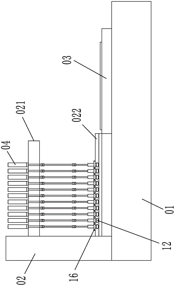
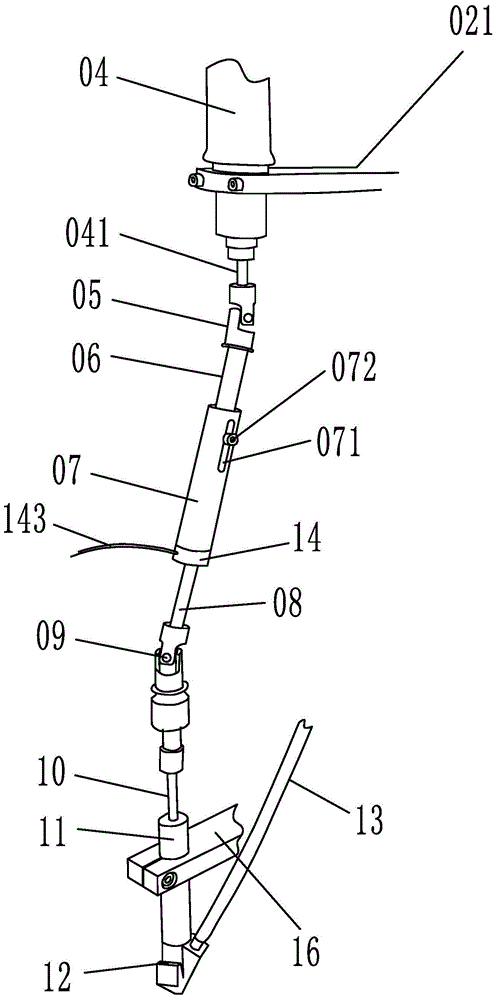
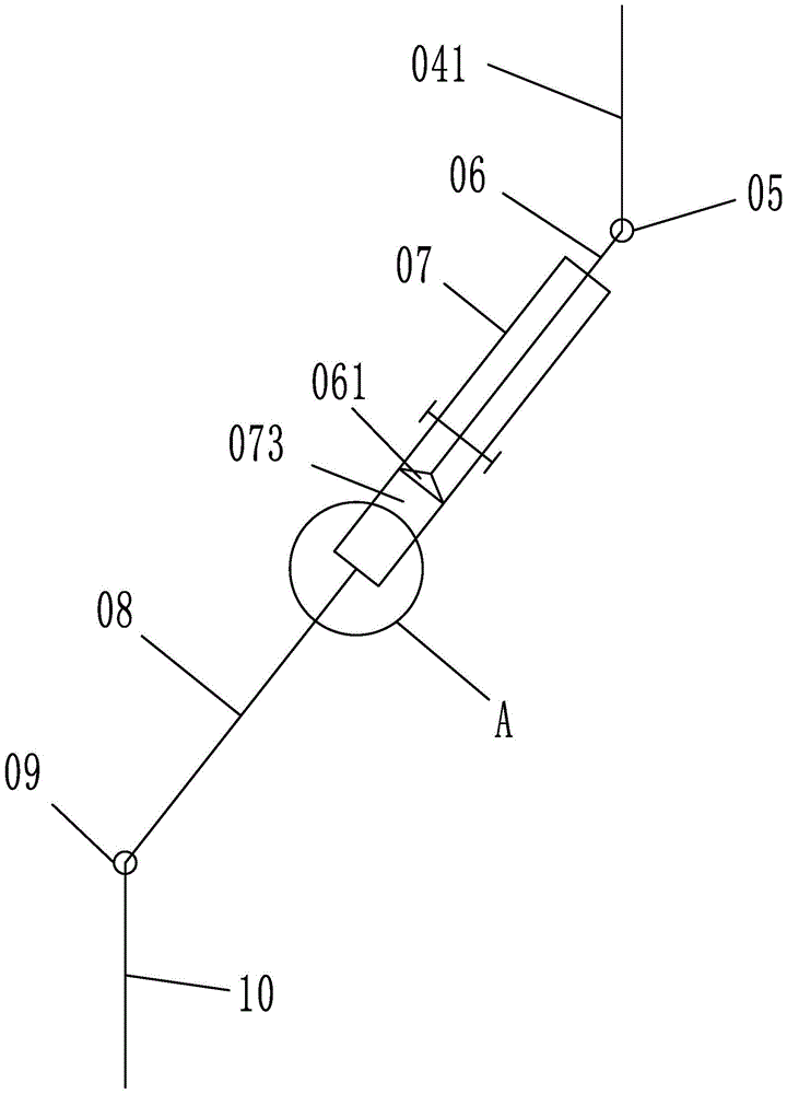
[0024] Embodiment 1: as figure 1 , 2 As shown in , 3, a screw lock payment system includes a frame 01, a feed system 03 and a lifting system 02 are arranged on the frame, an upper lifting frame 021 and a lower lifting frame 022 are connected to the lifting system, and the top of the upper lifting frame There are several motors 04 arranged vertically, the drive shaft 041 of the motor is connected with the first coupling 05, the angle between the motor drive shaft and the telescopic shaft is 160°, and the lower end of the first coupling is connected with a telescopic shaft, the lower end of the telescopic shaft is connected with the connecting shaft 08, the lower end of the connecting shaft is connected with the second coupling 09, the lower end of the second coupling is connected with the screw lock knife 10, and the outer side of the screw lock knife is provided with a positioning sleeve 11. The positioning sleeve is fixed on the lower lifting frame. The lower end of the posi...

Embodiment 2

[0026] Embodiment 2: The structure of this embodiment is basically the same as that of Embodiment 1, the difference is that, as Figure 10 As shown, there are five pulse gas charging holes 075 on the lower end surface of the fixed shaft. The pulse gas inlet holes are distributed in a circular arc. The radius length of the air intake cavity is the same. One end of the sliding shaft inside the fixed shaft is provided with a piston that matches the diameter of the air chamber. When the gas volume in the air chamber increases, the piston can be pushed to move, thereby realizing the relative movement between the sliding shaft and the fixed shaft, and elongating the telescopic shaft; When the amount of gas in the air chamber decreases, it can attract the movement of the piston, and then shrink the telescopic shaft. The outer sleeve of the connecting shaft is provided with an air intake sleeve, which is connected with the connecting shaft through a rotating bearing. When the connect...


PUM


Abstract

The invention relates to a tool device, in particular to a screw locking system. The screw locking system comprises a rack. A feeding system and an elevating system are arranged on the rack. An elevating rack and a lower elevating rack are connected to the elevating system. Multiple longitudinally-arranged motors are arranged on the top end of the upper elevating rack. The driving shaft of the motor is connected with a first shaft coupling. The lower end of the first shaft coupling is connected with a telescoping shaft. The lower end of the telescoping shaft is connected with a connection shaft. The lower end of the connection shaft is connected with a second shaft coupling. The lower end of the second shaft coupling is connected with a screw locking knife. The telescoping shaft comprises a slide shaft connected with the first shaft coupling and a static shaft sleeving the outer side of the slide shaft. One end, away from the slide shaft, of the static shaft is coaxially fixed on the connection shaft. A slide groove is arranged in the side wall of the static shaft. The slide groove is parallel to the axis of the static shaft. A guiding bolt penetrates through the slide groove. According to the invention, the beneficial effects are that the screw locking system is capable of locking multiple screws simultaneously; same locking torque is ensured; assembly efficiency is increased; and assembly time is saved.

Description

technical field [0001] The invention relates to a tooling device, in particular to a screw locking system. Background technique [0002] Screw fixing is a commonly used fixing method in the prior art, but some workpieces need to be fixed by multiple screws, such as the assembly of lamps, which need to be assembled with more than a dozen or even dozens of screws. In the prior art, the mounting screws are installed manually, and are locked one by one with electric or pneumatic screw locking guns. This installation method needs to be assembled one by one, which takes a long time and has low assembly efficiency. Moreover, the torques of different screw locks on the same workpiece cannot be unified, and the assembly quality is low. Contents of the invention [0003] The present invention mainly aims at the above problems, and provides a screw locking system capable of simultaneously locking multiple screws, ensuring the same locking torque, improving assembly efficiency, and s...

Claims


Application Information

Patent Timeline
Patent Type & Authority Patents(China)
IPC IPC(8): B23P19/06
CPCB23P19/06
Inventor 付德才
Owner 宁波千亚照明有限公司
Why Eureka
Try Eureka