Disassembly and assembly pincers of engine valve lock

A technology for engine valves and locks, applied in pliers, hand-held tools, manufacturing tools, etc., can solve the problems of high cost, increased equipment cost, complex structure, etc., and achieve the effects of low production cost, quick disassembly and assembly, and accurate positioning

Inactive Publication Date: 2015-09-09
JIANGSU POLYTECHNIC COLLEGE OF AGRI & FORESTRY
View PDF9 Cites 3 Cited by
  • Summary
  • Abstract
  • Description
  • Claims
  • Application Information

AI Technical Summary

Problems solved by technology

At present, there is no specially designed tool for the loading and unloading of the valve lock plate. Not only is the operation complicated and difficult to start, but also the work efficiency is low, and the loading and unloading is laborious and time-consuming.
[0004] In order to solve this problem, the patent No. 200920026597.1 "Diesel Engine Valve Lock Plate Removal Tool" discloses a tool that can disassemble the valve lock plate. This tool makes the inverted U-shaped pressure frame squeeze the valve spring seat by pressing the pressure rod. , so that the end of the valve stem is exposed, and then the worker installs the valve lock piece on the valve stem, but this scheme uses the gaps on both sides of the inverted U-shaped pressure frame to manually install the valve lock piece on the valve stem. Ensure enough clearance for installation. The inverted U-shaped pressure frame should not be very wide, so the contact area with the valve spring seat will not be large, which will cause uneven force on the valve spring. In severe cases, the tool may still be bounced out. The problem, on the other hand, although this equipment can separate the valve stem from the valve spring seat, it still needs to manually install the valve lock piece, which can be used in the case of small quantity installation, and the efficiency is still not high when installing in batches
[0005] In order to solve the above problems, the patent No. 200920048811.3 "Pneumatic valve lock plate remover" discloses a valve lock plate remover powered by a cylinder, and the device can directly install the valve lock plate on the device, No manual operation is required, but the structure of the equipment is complex and the cost is high. For a small enterprise, increasing the cost of the equipment means increasing the cost of the product, which is not conducive to sales or development of the enterprise. Therefore, combining the above problems, a structural A simple, low-cost tool that can quickly disassemble and assemble the valve lock plate

Method used


Image

  • Disassembly and assembly pincers of engine valve lock
  • Disassembly and assembly pincers of engine valve lock
  • Disassembly and assembly pincers of engine valve lock

Examples


Embodiment 1

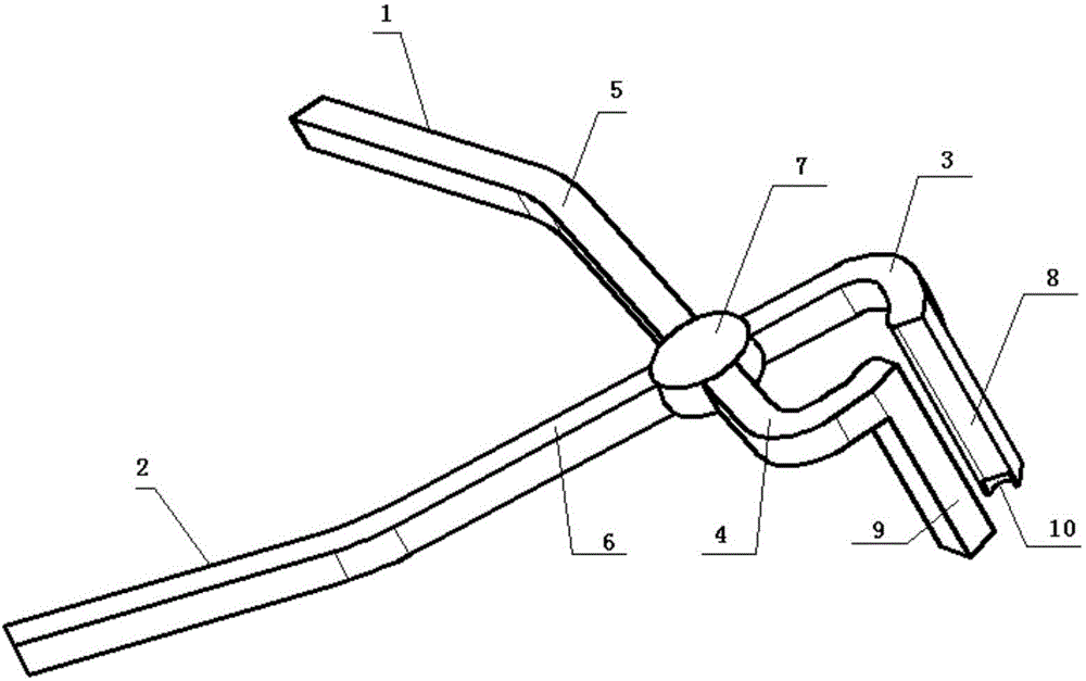
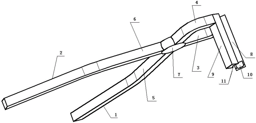
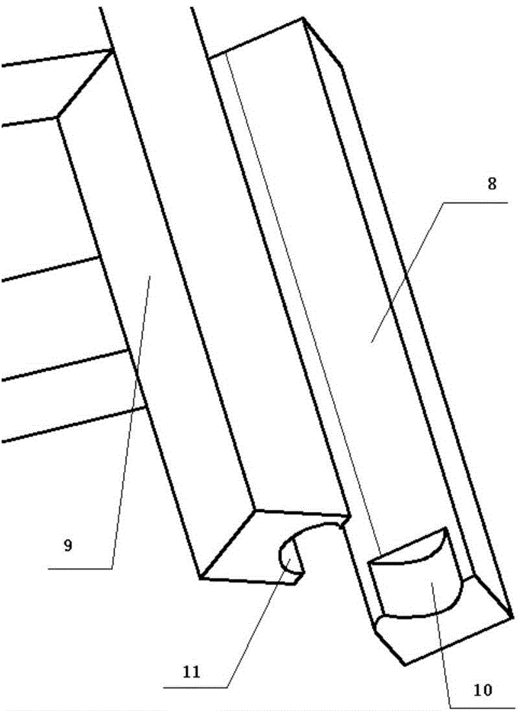
[0027] Such as Figure 1-3 Shown, a kind of pliers for removing and installing the engine valve lock plate comprises a first pliers handle 1, a second pliers handle 2, a movable fulcrum 7, a first vertical arm 8 and a second vertical arm 9; the first pliers handle 1, The second pliers handle 2 is arranged crosswise, and the movable fulcrum 7 is set at the intersection of the first pliers handle 1 and the second pliers handle 2; the first vertical arm 8 and the second vertical arm 9 are respectively arranged on the first pliers handle 1 and the second pliers handle The ends of the handle 2 are vertically connected to the first handle 1 and the second handle 2 respectively; the first handle 1 includes the first long rod 5 and the first short rod 3, and the second handle 2 includes the second Long rod 6 and the second short rod 4; The connecting points of the first long rod 5 and the first short rod 3, the second long rod 6 and the second short rod 4 are all located in the movabl...

Embodiment 2

[0038] It is basically the same as the embodiment 1, except that the length ratio of the first short rod 3 and the second short rod 4 to the first long rod 5 and the second long rod 6 is 1:5.


PUM


Abstract

The invention discloses a kind of disassembly and assembly pincers of an engine valve lock, which comprises a first pincer handle, a second pincer handle, a movable supporting point, a first perpendicular arm and a second perpendicular arm, wherein the first pincer handle and the second pincer handle are disposed in a crossed manner, and the movable supporting point is disposed at the intersection point of the first pincer handle and the second pincer handle; and the first perpendicular arm and the second perpendicular arm are respectively disposed on end heads of the first pincer handle and the second pincer handle, and top ends of the first perpendicular arm and the second perpendicular arm are respectively perpendicular to and connected to the first pincer handle and the second pincer handle. The disassembly and assembly pincers of the engine valve lock provided by the invention is simple in structure and low in cost, is operated easily and positioned accurately and conveniently, can quickly realize disassembly and assembly of the valve lock, can firmly clamp the valve lock in a groove at the tail part of the valve, avoids the valve from falling into an air cylinder due to loose fixation between the valve lock and a valve spring upper base, can reduce burdens of car repair staffs, and is very applicable for popularization.

Description

technical field [0001] The invention relates to a pliers for removing and installing an engine valve lock plate. Background technique [0002] The valve lock piece is stuck in the groove at the tail of the valve, and its function is to lock the spring seat and the valve stem under the action of the valve spring force, so that the spring force acts on the valve stem. The valve seat and the sealing tapered surface of the valve head cooperate to seal the cylinder, and the heat of the valve head is also transmitted outside through the valve seat. The valve seat can be directly bored out on the cylinder head or the cylinder block, or it can adopt a mosaic structure. The inlaid structure valve seats are all made independently of better materials (alloy cast iron, austenitic stainless steel, etc.). The function of the valve spring is to ensure the return of the valve. When the valve is closed, the seal between the valve and the valve seat is guaranteed. When the valve is opened, ...

Claims


Application Information

Patent Timeline
Patent Type & Authority Applications(China)
IPC IPC(8): B25B27/14B25B7/00
CPCB25B27/146B25B7/00
Inventor 高超学吴丽刘永华戴有华徐慕琪何志伟顾凯文俞冬辉顾金鹏陈国炎张锁荣
Owner JIANGSU POLYTECHNIC COLLEGE OF AGRI & FORESTRY
Why Eureka
Try Eureka