
Tempered glass homogenizing furnace

A technology for tempering glass and homogenizing furnace, applied in glass tempering, glass manufacturing equipment, manufacturing tools and other directions, can solve the problems of uneven temperature, waste, increase equipment investment, etc., to achieve convenient installation and maintenance, quality assurance, temperature uniformity Effect

Inactive Publication Date: 2015-09-09
肥西县三星玻璃有限公司
View PDF3 Cites 1 Cited by
  • Summary
  • Abstract
  • Description
  • Claims
  • Application Information

AI Technical Summary

Problems solved by technology

[0002] The non-vitreous substance particles inside the tempered glass are the most important factor leading to the self-explosion of the tempered glass. This substance is brought into the glass by impurities in the raw materials for glass production. The homogeneous treatment of tempered glass for secondary heating and annealing is a recognized solution. The most effective way to self-explode tempered glass is that the current glass homogeneous furnace is a three-dimensional hollow box with a fan on it. When working, the glass sheet is pushed into the furnace from the furnace door, the power is turned on, the heat is released, and the fan is turned on to make the inside of the box The temperature is uniform, and the homogenization process can be completed after a certain period of time at a certain temperature. This kind of homogenization furnace has certain problems. Because the fans are installed on the upper part of the furnace and blow air from top to bottom, the convection effect is not good. The temperature is uneven, and the temperature is controlled by the experience of the workers during the heating process. The poor temperature control affects the homogeneity effect of the tempered glass, and the existing furnace doors are all open, and the opening of the furnace door takes a certain amount of time. When the internal volume of the homogeneous furnace box is not enough, the furnace door needs to be disassembled and the furnace body is connected, which increases the investment of equipment and brings huge waste

Method used


Image

  • Tempered glass homogenizing furnace

Examples


Embodiment Construction

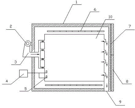
[0008] refer to figure 1 , the specific embodiment adopts the following technical solutions: it includes a homogeneous furnace body 1, a fan 2, an air supply pipe 3, a temperature display device 4, a temperature sensor 5, a heating pipe 6, a slide rail 7, a sliding door 8, and an air outlet 9 and an inner cavity 10, the interior of the homogeneous furnace body 1 is provided with an inner cavity 10, the upper and lower sides of the inner cavity 10 are provided with heating pipes 6, and the left side wall of the homogeneous furnace body 1 is provided with a fan 2, The fan 2 is connected with the air supply pipe 3, and the air supply pipe 3 communicates with the inner cavity 10, and a slide rail 7 is arranged on the right side wall of the homogeneous furnace body 1, and the slide rail 7 is slidably connected with the sliding door 8, and the homogeneous An air outlet 9 is arranged on the lower right side of the furnace body 1 .

[0009] A temperature sensor 5 is arranged at the b...


PUM


Abstract

Relating to tempered glass processing equipment, the invention provides a tempered glass homogenizing furnace. The upper side and lower side of an inner cavity (10) are provided with a heating pipe (6), the left side wall of the homogenizing furnace body (1) is provided with a fan (2), the fan (2) is in connection with a blastpipe (3), and the blastpipe (3) is communicated with the inner cavity (10), the right side wall of the homogenizing furnace body (1) is provided with a slide rail (7), the slide rail (7) and a double acting door (8) are in sliding connection, and an air outlet (9) is disposed at the lower part of the homogenizing furnace body (1) on the right side. The tempered glass homogenizing furnace has the characteristics of simple structure, convenient installation and maintenance, and uniform in-furnace temperature, also is provided with a temperature control system, has no need of heating by means of worker experience, and ensures the quality of tempered glass. At the same time, the furnace door adopts sliding open-close, does not occupy space, and is suitable for furnace body butt joint.

Description

Technical field: [0001] The invention relates to a tempered glass processing equipment, in particular to a tempered glass homogenization furnace. Background technique: [0002] The non-vitreous substance particles inside the tempered glass are the most important factor leading to the self-explosion of the tempered glass. This substance is brought into the glass by impurities in the raw materials for glass production. The homogeneous treatment of tempered glass for secondary heating and annealing is a recognized solution. The most effective way to self-explode tempered glass is that the current glass homogeneous furnace is a three-dimensional hollow box with a fan on it. When working, the glass sheet is pushed into the furnace from the furnace door, the power is turned on, the heat is released, and the fan is turned on to make the inside of the box The temperature is uniform, and the homogenization process can be completed after a certain period of time at a certain temperatu...

Claims


Application Information

Patent Timeline
IPC IPC(8): C03B27/012
Inventor 不公告发明人
Owner 肥西县三星玻璃有限公司
Learn More