Intermittent shaft bottom pressure difference reduction sub

A bottom-hole differential pressure, intermittent technology, applied in drilling equipment, earthwork drilling, drill pipe, etc., can solve the problems of harsh application conditions, high process requirements, and no popularization and application, and achieves the improvement of jet depressurization effect. Application prospect, effective and feasible effect of work

Inactive Publication Date: 2015-09-09
CHINA UNIV OF PETROLEUM (EAST CHINA)
View PDF7 Cites 4 Cited by
  • Summary
  • Abstract
  • Description
  • Claims
  • Application Information

AI Technical Summary

Problems solved by technology

Jet-type hydraulic decompression technology and negative pressure pulse jet decompression technology have not been popularized and applied due to their complex structure, high process requirements, and relatively harsh application conditions.

Method used


Image

  • Intermittent shaft bottom pressure difference reduction sub

Examples


Embodiment Construction

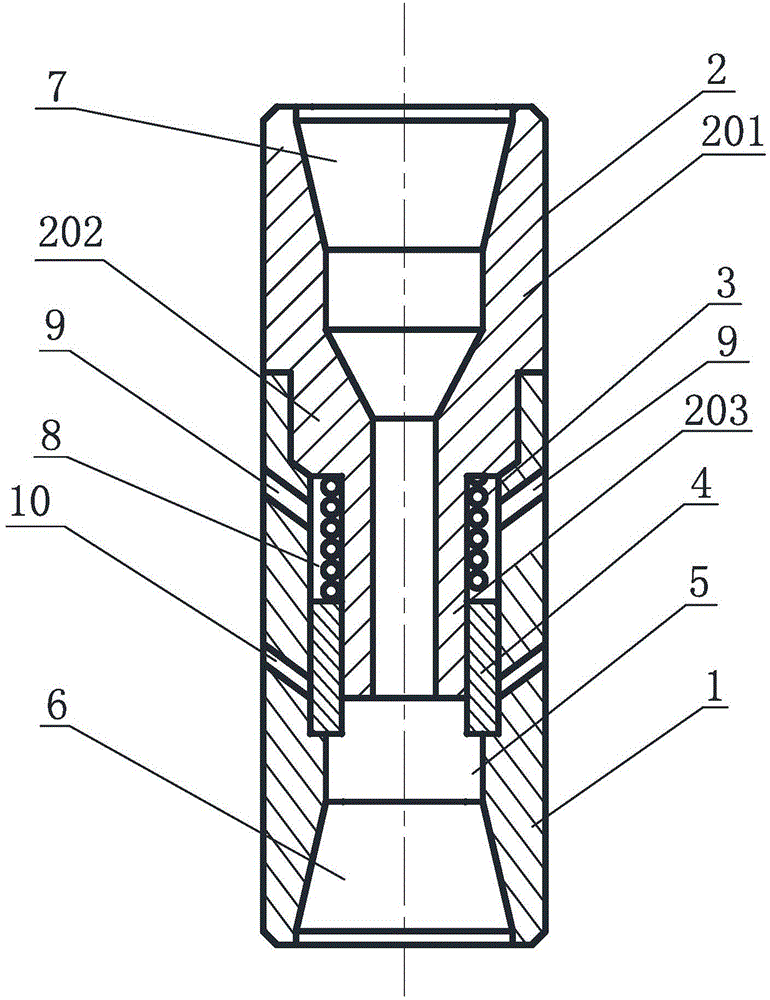
[0023] With reference to the accompanying drawings, an intermittent bottomhole pressure drop nipple includes an outer cylinder 1 , a drill pipe joint 2 , a spring 3 and an annular piston 4 . The outer cylinder 1 is provided with a through shaft hole 5 along its axial direction, the lower end of the outer cylinder 1 is provided with a water outlet 6 and a screw thread for connecting a drill bit, and the upper end of the outer cylinder 1 is connected with a drill pipe joint 2 . The drill pipe joint 2 is mainly composed of three cylinders with different diameters, namely the upper cylinder 201 of the drill pipe joint, the middle cylinder 202 of the drill pipe joint and the lower cylinder 203 of the drill pipe joint. The axial direction is sequentially connected and fixed downwards. The drill pipe joint 2 is partially inserted into the shaft hole. The outer wall of the cylinder in the middle of the drill pipe joint and the circumference of the inner wall of the outer cylinder are p...


PUM


Abstract

The invention discloses an intermittent shaft bottom pressure difference reduction sub. The sub comprises an outer cylinder, a drill rod joint, a spring and a circular piston. A through axle hole is formed in the outer cylinder axially, the upper end of the outer cylinder is connected with the drill rod joint, part of the drill rod joint is inserted in the axle hole, and a water flow channel is formed in the center of the drill rod joint axially. The spring and the circular piston are sleeved on the lower portion of the drill rod joint and capable of moving along the axis vertically, the upper end of the spring is connected with the drill rod joint, and the lower end of the spring is connected with the upper end of the circular piston. Pressure release holes and reverse nozzles are formed in the side wall of the outer cylinder, the pressure release holes are communicated with a chamber, the upper end of the circular piston is subjected to external annular pressure, the lower end of the circular piston is subjected to drilling liquid pressure in the axial hole, and the reverse nozzles are communicated with the axle hole when the circular piston moves upwards for certain distance under the action of the pressure difference on the upper and lower ends. By means of the sub, the shaft bottom pressure difference reduction effect can be improved, the drilling speed of drilling machinery is improved, and the shaft bottom cleaning auxiliary rock fracture capacity of bit nozzles is improved.

Description

technical field [0001] The invention relates to a pressure-reducing and speed-increasing tool for oil and gas drilling, in particular to an intermittent sub-joint for reducing the pressure difference at the bottom of a well. Background technique [0002] The bottom hole pressure difference refers to the pressure difference between the hydrostatic column pressure in the well and the formation pore pressure, which is one of the important factors affecting the increase of drilling speed. Laboratory experiments and field practice show that the ROP will decrease significantly with the increase of the bottom hole pressure difference. Broken, affecting the rock-breaking efficiency of the drill bit. When drilling in low-permeability rock formations, the bottom hole pressure difference has a greater impact on drilling speed than in high-permeability rock formations, because it is difficult for drilling fluid to enter the pores of low-permeability rock formations and cannot be balanc...

Claims


Application Information

Patent Timeline
Patent Type & Authority Applications(China)
IPC IPC(8): E21B17/02
Inventor 廖华林贾夏杨龑栋吴德松牛继磊
Owner CHINA UNIV OF PETROLEUM (EAST CHINA)
Why Eureka
Try Eureka