Oil nozzle

A technology of fuel injectors and nozzles, which is applied in the direction of engine components, delivery pipes/joints, engine lubrication, etc., and can solve the problems that lubricating oil cannot be sprayed to the preset position, wasting lubricating oil and compressed air, and reducing the lubricating effect , to achieve the effect of saving compressed air, preventing oil dripping and improving the utilization rate of lubricating oil

Active Publication Date: 2015-09-09
佛山市松广机械有限公司
View PDF8 Cites 5 Cited by
  • Summary
  • Abstract
  • Description
  • Claims
  • Application Information

AI Technical Summary

Problems solved by technology

like figure 1 As shown, the existing fuel injection nozzle is composed of a nozzle pipe and a fixing part. This structure has disadvantages: 1. When the air pressure of the compressed air is insufficient, the nozzle pipe will drip oil, resulting in a waste of lubricating oil and polluting the environment; 2. The lubricating oil is sprayed along the straight channel, and the lubricating oil at the spraying point is too dispersed, so that part of the lubricating oil cannot be sprayed to the preset position, resulting in waste of lubricating oil and compressed air; 3. The sprayed oil particles are uneven, which may easily cause fabric pollution or Oil needle; 4. There are a lot of yarn wadding in the air of the textile workshop, and the yarn wadding adheres to the outlet of the nozzle to form a film, which prevents the mixed oil and gas from spraying out and reduces the lubrication effect

Method used


Image

  • Oil nozzle
  • Oil nozzle
  • Oil nozzle

Examples


Embodiment Construction

[0020] The present invention will be described in further detail below in conjunction with the accompanying drawings.

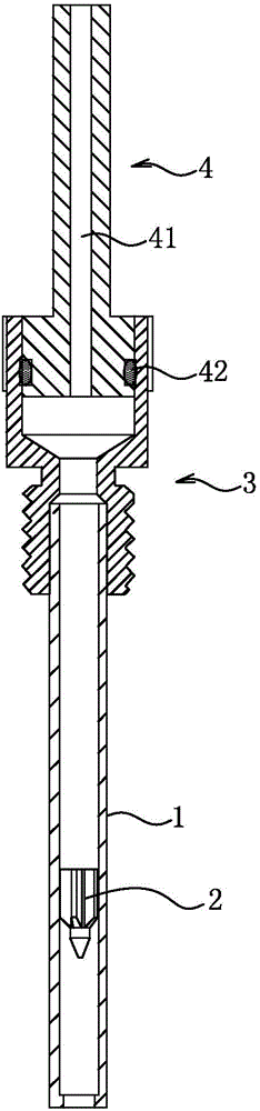
[0021] Figure 2-7 A fuel injector according to an embodiment of the invention is shown schematically.

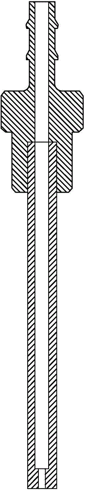
[0022] Such as figure 2 As shown, the fuel injector of this embodiment includes a nozzle 1 , a guide body 2 and a sleeve body 3 , the end of the nozzle tube 1 is connected to the sleeve body 3 , and the guide body 2 is located in the nozzle tube 1 .

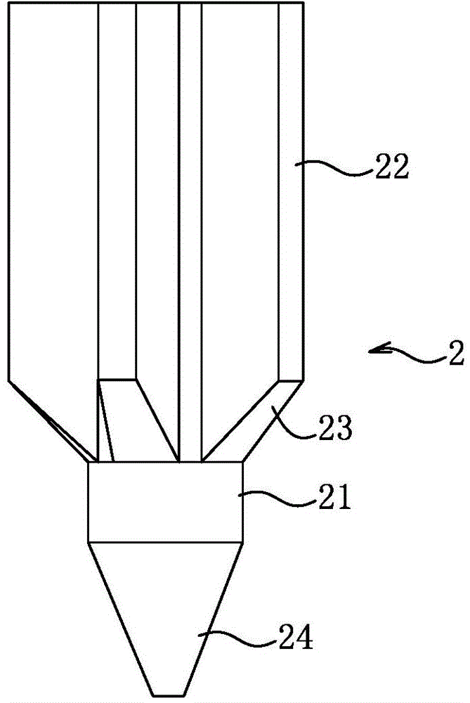
[0023] Such as image 3 and Figure 4 As shown, the guide body 2 includes a central cylinder 21 and a plurality of guide vanes 22 , and the plurality of guide vanes 22 are axially arranged on the outer surface of the central cylinder 21 . The central cylinder 21 and the deflector 22 are of an integral structure. An inclined surface 23 is provided on the end of the deflector 22 close to the outlet of the nozzle 1 . A plurality of guide vanes 22 are evenly distributed on the outer surface of the central ...


PUM


Abstract

The invention discloses an oil nozzle. The oil nozzle comprises a spraying tube, a flow guider and a sleeve, wherein an end of the spraying tube is connected with the sleeve; and the flow guider is positioned in the spraying tube. By the flow guider, pressure intensity of an oil and gas mixture in the spraying tube can be increased, sprayed lubricating oil can be gathered, the use ratio of the lubricating oil is increased, sprayed oil drops are uniform, the using amount of compressed air is reduced, and the oil nozzle is energy-saving and environment-friendly.

Description

technical field [0001] The invention relates to textile machinery, in particular to an oil spray nozzle for spraying lubricating oil. Background technique [0002] Lubricating oil is very important in textile machinery, especially for the lubrication of the needles of knitting machines. It is required to have a good lubricating effect and not pollute the textiles. Generally, compressed air is used to spray the lubricating oil to the knitting machine through the oil nozzle. Such as figure 1 As shown, the existing fuel injection nozzle is composed of a nozzle pipe and a fixing part. This structure has disadvantages: 1. When the air pressure of the compressed air is insufficient, the nozzle pipe will drip oil, resulting in a waste of lubricating oil and polluting the environment; 2. The lubricating oil is sprayed along the straight channel, and the lubricating oil at the spraying point is too dispersed, so that part of the lubricating oil cannot be sprayed to the preset positi...

Claims


Application Information

Patent Timeline
Patent Type & Authority Applications(China)
IPC IPC(8): F16N21/02
Inventor 任钊良
Owner 佛山市松广机械有限公司
Why Eureka
Try Eureka