
Garbage incinerator and garage disposal method

A waste incinerator and waste technology, which is applied in the combustion method, incinerator, combustion type, etc., can solve the problems of low treatment efficiency, low treatment efficiency, insufficient incineration, etc., and achieves continuous feeding operation and convenient feeding. Volume, easy to adjust the effect

Inactive Publication Date: 2015-09-09
聂超
View PDF7 Cites 1 Cited by
  • Summary
  • Abstract
  • Description
  • Claims
  • Application Information

AI Technical Summary

Problems solved by technology

[0002] In the process of garbage disposal, garbage incineration is used for treatment. Usually, the incineration is insufficient due to the blocky structure of the garbage, which makes the treatment efficiency low. At the same time, the existing garbage incinerator has a complex structure, inconvenient operation, and low treatment efficiency. For the occasion of small waste disposal, the existing waste incinerator takes up a lot of space and the utilization rate is not high

Method used


Image

  • Garbage incinerator and garage disposal method

Examples


Embodiment 1

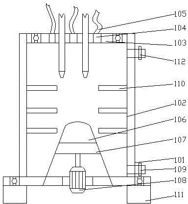
[0029] Such as figure 1 As shown, a garbage incinerator includes a furnace body 101 and a furnace lining 102 arranged on the inner wall of the furnace body 101;

[0030] A material distribution tray 103 is arranged on the upper end surface of the furnace body 101, and the described material distribution tray 103 is connected with the upper end surface of the furnace body 101 through a bearing, and a flame nozzle is arranged on the described material distribution tray 103;

[0031] At least 6 star valves 104 are arranged on the material distribution tray 103, and the star valves 104 are respectively connected with feeding pipes 105 for feeding;

[0032] A material distribution cone 106 is arranged in the middle of the furnace body 101, a ring gear 107 is fixedly connected to the outer wall of the furnace body 101 below the material distribution cone 106, and a driving motor 108 is arranged at the bottom of the furnace body 101. , the drive motor 108 drives the ring gear 107 to...

Embodiment 2

[0038] The present invention also discloses a kind of garbage incinerator garbage treatment method on the basis of embodiment 1, comprises the following steps:

[0039] S1: Open the star valve, add garbage to be processed into the furnace body 101 through at least 6 feeding pipes 105, and the garbage to be processed enters the furnace body 101 through the distribution tray 103, and the garbage stock in the furnace body 101 reaches the maximum value , close the star valve to close the body of furnace 101, start the drive motor 108, and drive the body of furnace 101 to rotate, and the garbage will fall in a scattered state under the centrifugal force of the material dividing plate 110 and the body of furnace 101 rotating;

[0040] S2: Burn the garbage in the furnace body, use the burner nozzle to burn the garbage in the furnace body 101, stop driving the motor 108 after the garbage is fully burned, and output the garbage from the material output port to the furnace body 101;

[...


PUM


Abstract

The invention discloses a garbage incinerator. The garbage incinerator comprises a furnace body and a furnace lining arranged on the inner wall of the furnace body; the upper end of the furnace body is provided with a distribution disk, and the distribution disk is connected with the upper end face of the furnace body through a bearing; a flame nozzle is arranged on the distribution disk, and at least six star valves are arranged on the distribution disk, and baiting pipes for baiting are respectively connected to the star valves; the middle part of the furnace body is provided with a distribution cone, and the outer wall of the furnace body at the lower part of the distribution cone is fixedly connected to a tooth ring; the lower part of the furnace body is provided with a driving motor, and the driving motor drives the tooth ring to rotate through the gear group. After dispersing garbage, the garbage enters the garbage incinerator to perform the incineration work; thus the garbage incinerator can accelerate the garbage disposal process and improve the disposal efficiency.

Description

technical field [0001] The invention relates to a garbage incinerator and a garbage treatment method. Background technique [0002] In the process of garbage disposal, garbage incineration is used for treatment. Usually, the incineration is insufficient due to the blocky structure of the garbage, which makes the treatment efficiency low. At the same time, the existing garbage incinerator has a complex structure, inconvenient operation, and low treatment efficiency. For occasions of small-scale waste disposal, the existing waste incinerator occupies a large space and has a low utilization rate. Contents of the invention [0003] The purpose of the present invention is to provide a garbage incinerator and a garbage treatment method, which can improve the defects of the prior art, and after the garbage is dispersed, it can be put into the incinerator for incineration, which can speed up the garbage treatment process and improve the treatment efficiency. [0004] The present ...

Claims


Application Information

Patent Timeline
IPC IPC(8): F23G5/00F23G5/44
CPCF23G5/00F23G5/444
Inventor 聂超
Owner 聂超
Features
  • Generate Ideas
  • Intellectual Property
  • Life Sciences
  • Materials
  • Tech Scout
  • Unparalleled Data Quality
  • Higher Quality Content
  • 60% Fewer Hallucinations
Learn More