Atmosphere remote sensing laser radar optical receiving device based on telescope arrays

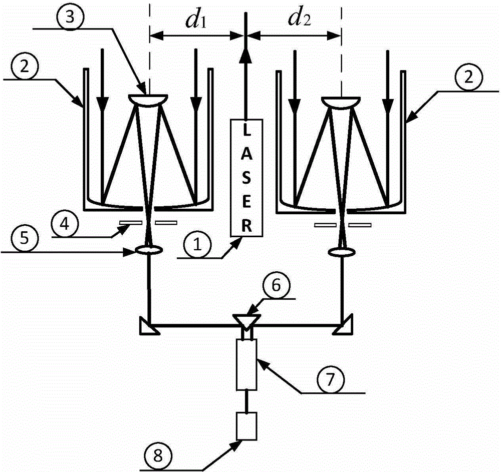
A laser radar and optical receiving technology, which is used in measurement devices, climate sustainability, and re-radiation of electromagnetic waves. It can solve the problems of the upper limit of the size of large-diameter telescopes and the difficulty of processing, and increase the echo signal strength and effective detection range. Effect

Inactive Publication Date: 2015-09-09
ZHEJIANG UNIV
View PDF5 Cites 7 Cited by
  • Summary
  • Abstract
  • Description
  • Claims
  • Application Information

AI Technical Summary

Problems solved by technology

However, the processing difficulty of large-aperture telescopes is much higher than that of small-aperture telescopes, so its price is several times or even dozens of times that of small-aperture telescopes, and there is an upper limit to the size of large-aperture telescopes

Method used


Image

  • Atmosphere remote sensing laser radar optical receiving device based on telescope arrays
  • Atmosphere remote sensing laser radar optical receiving device based on telescope arrays
  • Atmosphere remote sensing laser radar optical receiving device based on telescope arrays

Examples


Embodiment Construction

[0022] The present invention is further analyzed below in conjunction with specific examples.

[0023] The basic lidar equation is

[0024] P ( r ) = CY ( r ) A r 2 β ( r ) T 2 ( r ) , - - - ( 2 )

[0025] In the formula, P(r) represents the intensity of the echo signal, C represents the system constant, including the energy of the emitted laser, the transmittance of the system, etc., Y(r) is the overlap factor between the emitted laser and the field of view of the telescope, and β(r) represents Backscatter coefficient, T 2 (r) refers to the atmospheric extinc...


PUM


Abstract

The invention discloses an atmosphere remote sensing laser radar optical receiving device based on telescope arrays. According to the invention, a problem that echo signals are weak and detection distances are limited caused by small receiving area of single telescope in a laser radar can be solved. In the invention, the single telescope in the laser radar is replaced by multiple combinations of telescopes, and via the symmetrically arranged receiving optical paths and through specially designed reflecting prisms, it is ensured that back scattering echo signals which are received by different telescopes and generate in the same area are synchronously recorded by a photoelectric detector and array of the telescopes are equivalent to a telescope with larger caliber, thereby increasing echo signal intensity and effective detection scope of the system via bigger receiving area. Compared with a method of increasing caliber of a single telescope, cost can be greatly reduced via the telescope array method. The method is applicable for all laser radar systems using telescopes as receivers, and provides a new direction for promotion and development of laser radar technology.

Description

technical field [0001] The invention relates to a laser radar, in particular to an optical receiving device for an atmospheric remote sensing laser radar based on a telescope array. Background technique [0002] Atmospheric remote sensing lidar technology is an active real-time detection technology. Its basic principle is to emit a beam of high-quality laser light to the target atmosphere, use telescopes and other devices to receive backscattered echo signals of various particles, and pass optical components and The electronic device analyzes and compares the echo signals, and finally retrieves useful information such as the type, concentration, motion state and temperature of particles in the atmosphere. The main difficulty of lidar technology is that the intensity of the echo signal is too weak, which makes it have high requirements for laser pulse energy, telescope receiving area, optical components and electronic devices, which leads to high cost of lidar system. If you...

Claims


Application Information

Patent Timeline
Patent Type & Authority Applications(China)
IPC IPC(8): G01S7/481G01S7/486G01S17/95
CPCG01S7/4816G01S7/486G01S17/95Y02A90/10
Inventor 刘东杨甬英罗敬周雨迪成中涛
Owner ZHEJIANG UNIV
Why Eureka
Try Eureka