Method for parallel-connection network access of cable branch box or ring main unit and T-shaped shunt device
A shunt device and cable connection technology, applied in circuits, electrical components, conductive connections, etc., can solve problems such as casualties, economic losses, power grid blackouts, etc., to facilitate domestic electricity consumption, reduce economic losses, and improve power supply reliability. Effect
- Summary
- Abstract
- Description
- Claims
- Application Information
AI Technical Summary
Problems solved by technology
Method used
Image

Examples
Embodiment 1
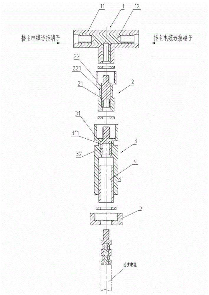
[0036] Embodiment one, such as figure 1 As shown, the T-shaped shunt device on the main power supply line disclosed in this embodiment mainly includes an I-shaped T-joint 1 , a butt joint 2 and an I-shaped linear connection terminal 3 .
[0037] The Ι-type T-joint 1 is an integral part of the Ι-type T-shaped inner conductor and the Ι-type T-shaped hard insulating sleeve 11 embedded with the Ι-type T-shaped inner conductor 12, and the Ι-type T-shaped hard insulating sleeve 11 is in three directions. The lengths are all greater than the length of the I-type T-shaped inner conductor 12, and the three ports all form an arc extinguishing chamber. The three ports of the Ι-type T-shaped internal conductor 12 are all threaded connection structures of internally threaded holes, and the threads at both ends of the head rotate in opposite directions.
[0038]The butt joint 2 is an integral part of an internal conductor 21 and a hard insulator 22 embedded with the internal conductor 21. ...
Embodiment 2
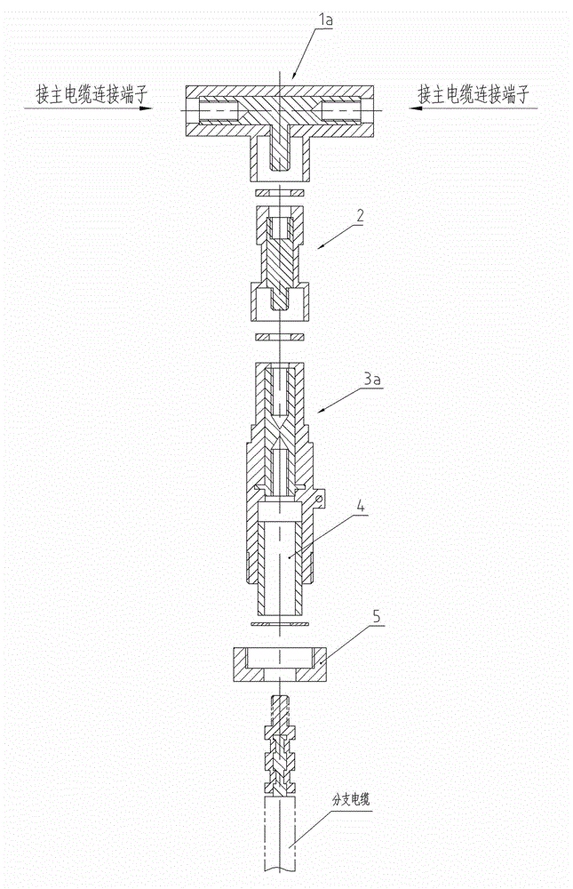
[0044] Embodiment two, such as figure 2 As shown, the T-shaped shunt device on the main power supply line disclosed in this embodiment mainly includes a Type II T-shaped joint 1a, a butt joint 2 and a Type II straight connection terminal 3a, and the Type II T-shaped joint 1a is the same as that in Embodiment 1. The difference between the Ι-type T-shaped joint 1 is that the rod connection structure of the T-shaped internal conductor is an external thread head, and the difference between the Ⅱ-type linear connection terminal 3a and the Ι-type linear connection terminal 3 in Embodiment 1 is that the two ends of the internal conductor The connection structures are all internal threaded holes, and the diameter of the outer wall of the arc extinguishing outer wall of the outer hard insulating sleeve is smaller than the diameter of the outer wall of the cable connection. The butt joint 2 is upside down with the arrangement in the first embodiment. Other structures and operations of...
Embodiment 3
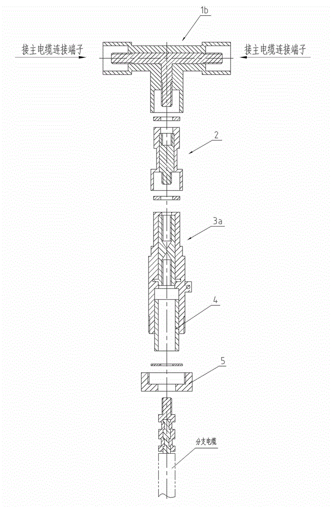
[0045] Embodiment three, such as image 3 As shown, the T-shaped shunt device on the main power supply line disclosed in this embodiment mainly includes a Type III T-joint 1b, a butt joint 2 and a Type II linear connection terminal 3a, and the T-shaped interior of the Type III T-joint 1b The connection structures of the three connection ends of the conductor are all external thread heads, and the inner diameters of the three ports of the T-shaped hard insulating sleeve are all larger than the outer diameters of the external thread heads. Other structures and operations of this embodiment are the same as those of Embodiment 2.
PUM
 Abstract
Description
Claims
Application Information
 - Generate Ideas
- Intellectual Property
- Life Sciences
- Materials
- Tech Scout
- Unparalleled Data Quality
- Higher Quality Content
- 60% Fewer Hallucinations
Browse by: Latest US Patents, China's latest patents, Technical Efficacy Thesaurus, Application Domain, Technology Topic, Popular Technical Reports.
© 2025 PatSnap. All rights reserved.Legal|Privacy policy|Modern Slavery Act Transparency Statement|Sitemap|About US| Contact US: help@patsnap.com