
Gear shifting equipment for motor vehicle transmissions

A technology for motor vehicles and transmissions, applied in mechanical equipment, components with teeth, transmission control and other directions, can solve the problems of large radial structure space, complex tools, consumption, etc., and achieve the effect of compact structure and saving structure space

Inactive Publication Date: 2016-12-28
SCHAEFFLER TECH AG & CO KG
View PDF6 Cites 0 Cited by
  • Summary
  • Abstract
  • Description
  • Claims
  • Application Information

AI Technical Summary

Problems solved by technology

Of course, deep-drawn sheet metal parts require expensive, complex tools and often multi-stage deep-drawing methods
[0007] The disadvantage of this embodiment is that the shifting device is relatively complex to produce
In addition, the ball lock and the elements that fasten the ball lock relative to the transmission housing require a relatively large radial installation space

Method used


Image

  • Gear shifting equipment for motor vehicle transmissions
  • Gear shifting equipment for motor vehicle transmissions
  • Gear shifting equipment for motor vehicle transmissions

Examples


Embodiment Construction

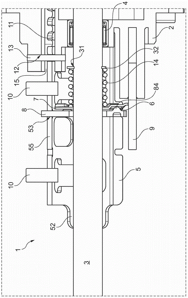
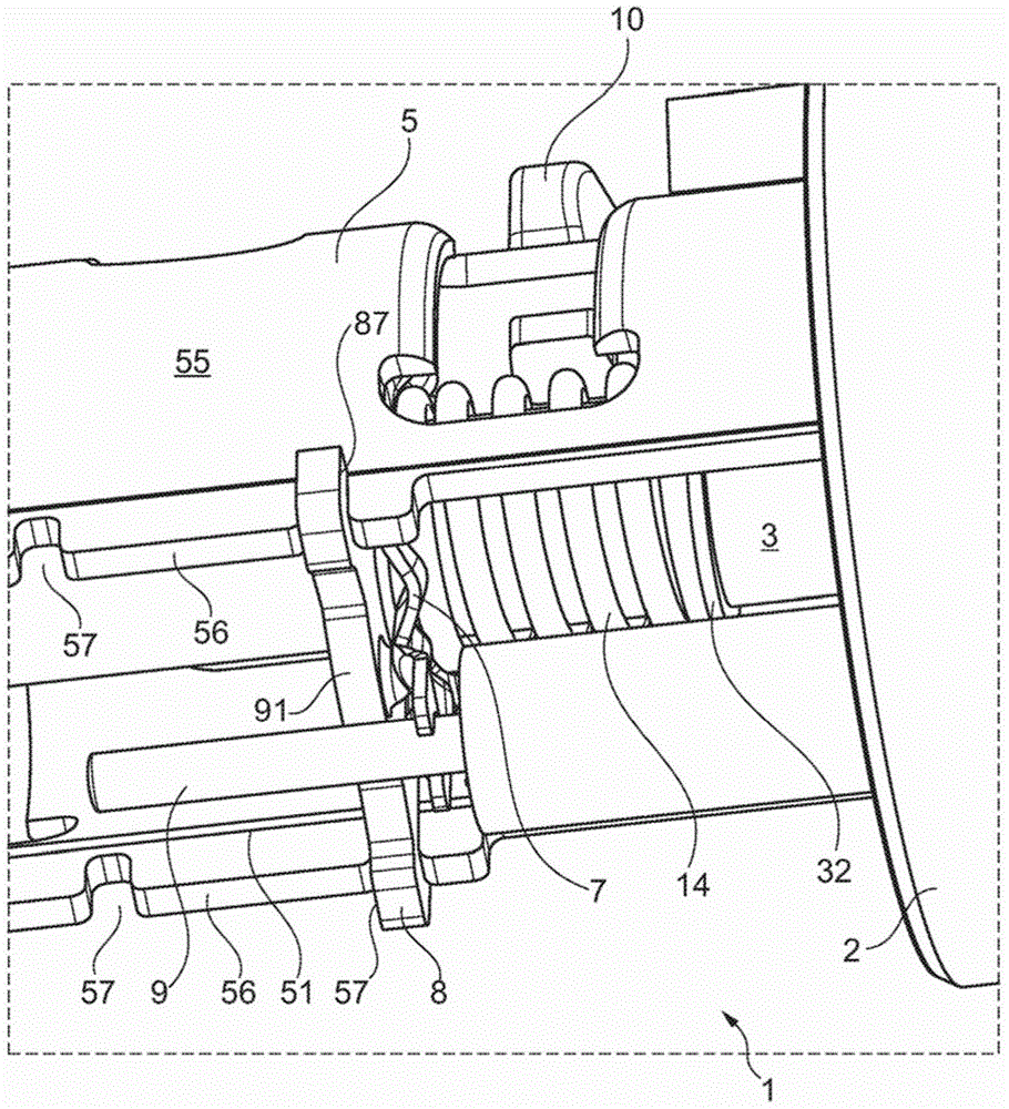
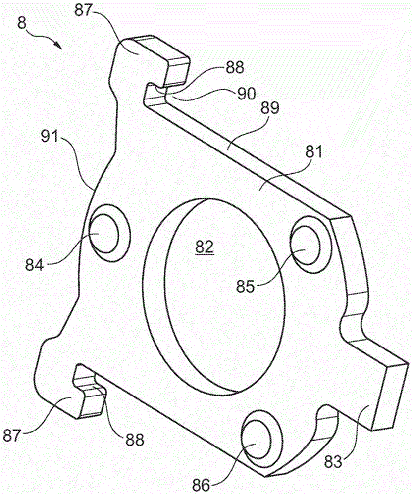
[0029] figure 1 and 2 The shifting device 1 is shown in the form of a shifting dome. The shift dome comprises: a flange-shaped housing part 2, which can be screwed onto a transmission housing not shown further; and a shift shaft 3, which is rotatably mounted on Housing part 2.

[0030] The shifting shaft 3 is mounted in the housing part 2 in a rolling manner via a bearing 4 and is rotatable relative to the housing part 2 . The rotation is introduced via a selector lever, not shown, which is kinematically connected to the selector shaft 3 and which is arranged on the housing 2 . The shift shaft 3 is fixed in the axial direction and cannot move. A low-friction displacement in the (axial) selector direction can thus be dispensed with, so that the bearing 4 is designed to absorb higher forces than a needle bearing.

[0031] The shifting sleeve 5 is arranged on the shifting shaft 3 in a rotationally fixed manner, but axially displaceable relative to one another. The shifting sl...


PUM


Abstract

The invention relates to a shifting device (1) of a motor vehicle change-speed gearbox, comprising a selector shaft (3), a housing part (2) on which said selector shaft (3) can be rotatably mounted, an engaging unit (6) for securing the selected positions, which comprises an engaging contour (74, 75) on a first engaging component (7) and a second engaging component (8) with an engaging element (84, 85, 86). Said components (7, 8) can be moved relative to each other and are locked counter to each other, and the engaging element (84, 85, 86) is pretensioned counter to the engaging contour (74, 75) parallel to the rotational axis.

Description

technical field [0001] The invention relates to a shifting device of a motor vehicle transmission, said shifting device having: a shift shaft; a housing part, with respect to which the shift shaft is mounted rotatably; A locking unit having a locking contour on a first locking component and a second locking component with a locking element, wherein the components are movable relative to one another and lockable relative to one another. Background technique [0002] Such a shifting device is known as a shifting dome of a motor vehicle gear transmission. The selector shaft forms an intermediate element when transmitting the driver's shifting and selection movements to the gearwheel to be shifted. Typically, the selection and shifting movement is transmitted via a movement of the shift shaft in the axial direction and a pivoting of the shift shaft about its longitudinal axis. [0003] The selector shaft usually has a gate guide which, in a positively guided function, allows o...

Claims


Application Information

Patent Timeline
Patent Type & Authority Patents(China)
IPC IPC(8): F16H61/24F16H63/30
CPCF16H61/24F16H2061/243F16H2063/3076
Inventor 约亨·勒费尔曼克劳斯·克拉默
Owner SCHAEFFLER TECH AG & CO KG
Learn More