Front-set micro-tillage machine with depth-limiting function
A micro-tiller, front-mounted technology, applied in the field of agricultural machinery, can solve the problems of high manufacturing difficulty, reduced work efficiency, decreased work efficiency, etc., and achieves the effects of reducing raw material and processing costs, convenient and fast processing, and reducing driving burden.
- Summary
- Abstract
- Description
- Claims
- Application Information
AI Technical Summary
Problems solved by technology
Method used
Image

Examples
Embodiment 1
[0044] The micro-tiller with a depth-limiting function according to the embodiment of the present invention, the micro-tiller includes:
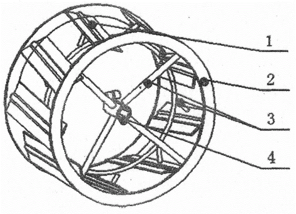
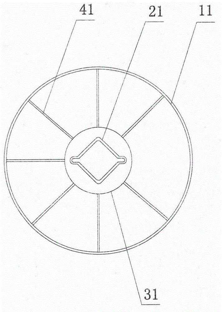
[0045] A power device (such as a diesel engine), a rotary tiller, and a handrail, the rotary tiller is arranged at the head of the tiller, that is, a front tiller;
[0046] a transmission device, the transmission device is arranged between the power device and the rotary tiller;
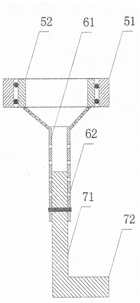
[0047] Rotating mechanism, the rotating mechanism is arranged at the lower part of the transmission device (as a fixed frame for fixing the rotating mechanism); the rotating mechanism can use components such as bearings, and the outer ring 51 of the bearing is fixed on the transmission device, such as figure 2 shown;
[0048] A support, the support is mounted on the rotating mechanism; for example, the support includes a horizontal part 72 and a vertical part 71, and is generally "L" shaped, such as figure 2 The horizontal section of the vertical portion 71 is ...
Embodiment 2
[0055] The micro-cultivator with the depth limiting function of the embodiment of the present invention is different from Embodiment 1 in that the adjusting component adopts a hydraulic device, the support is connected to the hydraulic device, and the power of the hydraulic device comes from a diesel engine.
Embodiment 3
[0057] The micro-cultivator with the depth-limiting function of the embodiment of the present invention is different from the embodiment 1 in that the bottom of the transmission device is provided with a blind hole, and one end of the tubular part is clamped into the blind hole, and one end of the tubular part is located in the blind hole. Free rotation in the blind hole without leaving the blind hole, so as to replace the bearing.
PUM
 Abstract
Description
Claims
Application Information
 - Generate Ideas
- Intellectual Property
- Life Sciences
- Materials
- Tech Scout
- Unparalleled Data Quality
- Higher Quality Content
- 60% Fewer Hallucinations
Browse by: Latest US Patents, China's latest patents, Technical Efficacy Thesaurus, Application Domain, Technology Topic, Popular Technical Reports.
© 2025 PatSnap. All rights reserved.Legal|Privacy policy|Modern Slavery Act Transparency Statement|Sitemap|About US| Contact US: help@patsnap.com