
Loop tension control method and device

A technology of tension control and looper, which is applied in the direction of rolling mill control devices, metal rolling, manufacturing tools, etc., can solve the problems of excessive tension difference between the two towers of the looper, strip slipping and loosening, etc.

Active Publication Date: 2015-09-16
SHOUGANG JINGTANG IRON & STEEL CO LTD
View PDF5 Cites 8 Cited by
  • Summary
  • Abstract
  • Description
  • Claims
  • Application Information

AI Technical Summary

Problems solved by technology

[0003] Aiming at the problems existing in the prior art, the embodiment of the present invention provides a looper tension control method and device, which is used to solve the technical problem in the prior art that the tension difference between the two towers of the looper is too large to cause the strip steel to slip and loosen

Method used


Image

  • Loop tension control method and device
  • Loop tension control method and device

Examples


Embodiment 1

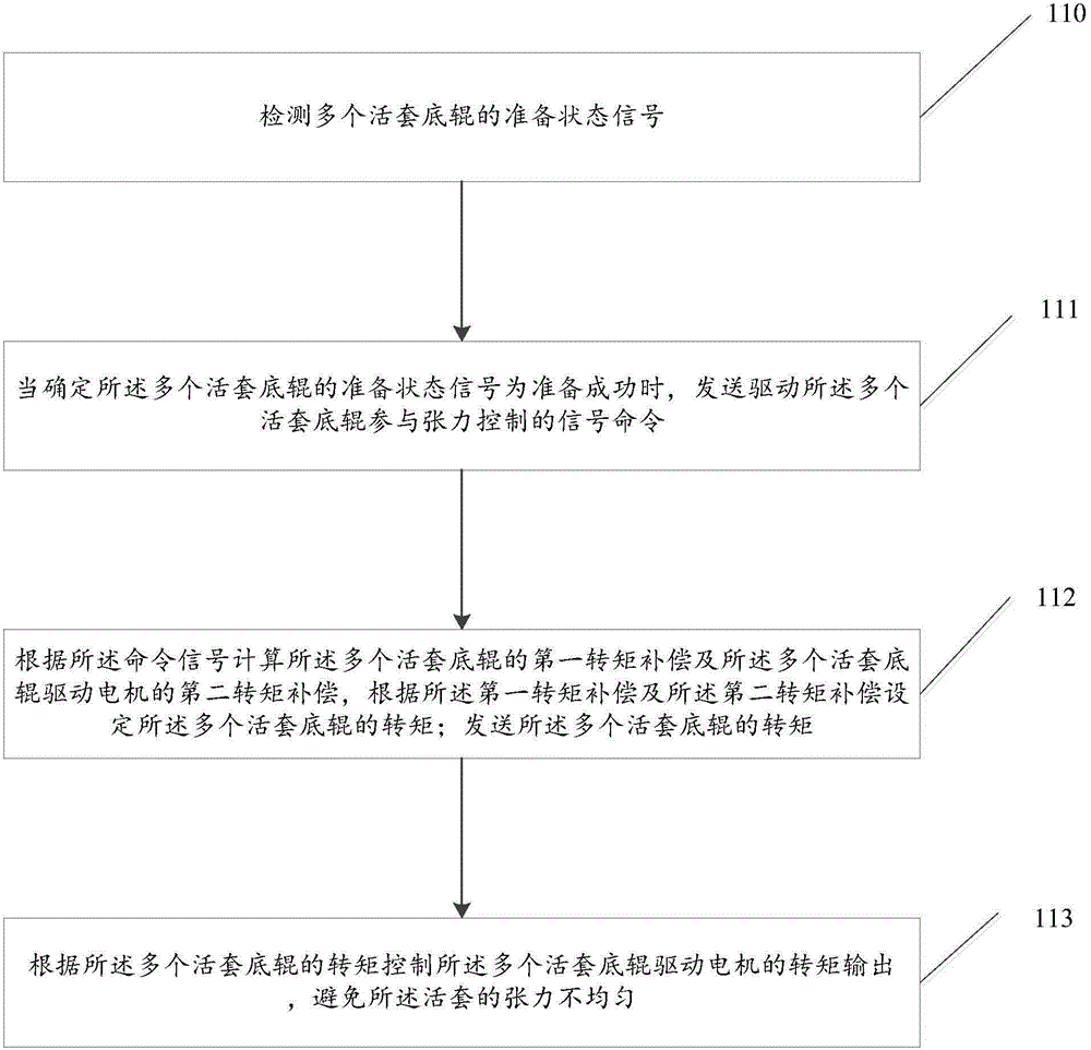
[0049] This embodiment provides a looper tension control method, such as figure 1 As shown, the method mainly includes the following steps:

[0050] Step 110, detecting readiness status signals of multiple looper bottom rollers;

[0051] In this step, the plurality of looper bottom rollers includes eight, and the detection unit detects the readiness status signals of the eight looper bottom rollers one by one. The readiness signal is a signal that the eight looper bottom rollers participate in tension control.

[0052] Step 111, when it is determined that the readiness signal of the plurality of looper bottom rollers is ready successfully, sending a signal command to drive the plurality of looper bottom rollers to participate in tension control;

[0053] In this step, after the detection unit detects the readiness signal of the eight looper bottom rollers, the readiness signal is sent to the determination unit, and the determination unit judges whether the readiness signal o...

Embodiment 2

[0083] Corresponding to Embodiment 1, this embodiment provides a looper tension control device, such as figure 2As shown, the device includes: a detection unit 21, a determination unit 22, and a control unit 23; wherein,

[0084] The detection unit 21 is used for detecting readiness signals of a plurality of looper bottom rollers. Specifically, the plurality of looper bottom rollers includes eight, and the detection unit 21 detects the readiness status signals of the eight looper bottom rollers one by one. The readiness signal is a signal that the eight looper bottom rollers participate in tension control.

[0085] The determining unit 22 is used to determine that when the readiness signal of the plurality of looper bottom rollers is preparation success, send a signal command to drive the plurality of looper bottom rollers to participate in tension control; calculate the The first torque compensation of the plurality of looper bottom rollers and the second torque compensati...


PUM


Abstract

The invention provides a loop tension control method and device. The method includes the steps of detecting preparation state signals of a plurality of loop bottom rollers, generating instruction signals for driving the loop bottom rollers to participate in tension control when determining that the preparation state signals of the loop bottom rollers are successfully prepared, calculating first torque compensation of the loop bottom rollers and second torque compensation of loop bottom roller drive motors according to the instruction signals, setting torques of the loop bottom rollers according to the first torque compensation and the second torque compensation, sending the torques of the loop bottom rollers, and controlling the torque output of the loop bottom roller drive motors according to the torques of the loop bottom rollers so that the tension non-uniformity of loops can be avoided. Thus, the technical problem that in the prior art, due to the fact that the loop double-tower tension difference is too large, strip steel slides and gets loose is solved.

Description

technical field [0001] The invention belongs to the technical field of iron and steel metallurgy, and in particular relates to a looper tension control method and device. Background technique [0002] In the field of iron and steel metallurgy technology, the inlet loop of the cold rolling continuous annealing unit adopts a double tower structure, and the double towers include 1# tower and 2# tower. In the tension control of the entrance looper, the hoist of the 2# tower is the main hoist, and the hoist of the 1# tower is the driven hoist, that is to say, the torque of the hoist of the 1# tower is the same as that of the hoist of the 2# tower. Therefore, in theory, the tension of tower 1 and tower 2 should be the same. However, in the actual production process, the bottom roll of the looper at the entrance loop acts as a driven roll and runs with the speed of the looper. In production, due to factors such as power loss of the bottom roll motor and roller friction, the variet...

Claims


Application Information

Patent Timeline
IPC IPC(8): B21B41/00B21B37/00
Inventor 李文波付友昌李冠雄张益滔刘顺明胡建军孙连生谭谨峰鲍成人赵志坚林英哲刘顺心
Owner SHOUGANG JINGTANG IRON & STEEL CO LTD
Learn More