Mechanical grab

A mechanical gripper and body technology, applied in the field of mechanical grippers, can solve the problems of uneven force, unsteady grasping of workpieces, and easy occurrence of safety accidents, and achieve the effect of uniform force and firm grasping.

Inactive Publication Date: 2015-09-16
SUZHOU BLUE KING MACHINE TOOL TECH CO LTD
View PDF7 Cites 24 Cited by
  • Summary
  • Abstract
  • Description
  • Claims
  • Application Information

AI Technical Summary

Problems solved by technology

[0002] In the field of industrial automation technology and many production fields, manipulators can be said to be very common. Although the structure of manipulators is different, the separation or gathering movement of the ends of the jaws generally revolves around one or several fulcrums. Therefore, the contact between the claw and the workpiece is generally point contact, so the grasping of the workpiece is not only not firm, but also due to uneven force, it is easy to damage the workpiece or the manipulator itself. In severe cases, even due to the grasping of the workpiece If it is not taken firmly, it is easy to cause a safety accident

Method used


Image

  • Mechanical grab

Examples


Embodiment Construction

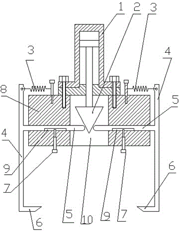
[0009] The described mechanical gripper comprises a piston cylinder (1), a spreader body (8), the spreader body (8) is a circle or a regular polygon, and the center of the body (8) has a A large through hole (10), the piston cylinder (1) is installed and fixed at a position just above the large through hole (10) of the spreader body (8), and the piston rod of the piston cylinder (1) is placed in the through hole (10) Inside, an inverted cone (2) is fixed on the piston rod of the piston cylinder (1), and two or more through holes uniformly distributed in the circumferential direction are formed in the circumferential diameter direction of the spreader body (8). A guide rod (5) is arranged in each through hole, the guide rod (5) is provided with a guide groove (9), and the head of the guide pin (7) installed on the spreader body (8) lies on into the groove (9), a moving arm (4) is fixed at the outer end of each guide rod (5), the moving arm (4) is parallel to the center li...


PUM


Abstract

The invention discloses a mechanical grab. The mechanical grab comprises a piston cylinder and a suspender body, a large through hole is formed in the center of the body, the piston cylinder is fixedly installed on the position over the large through hole of the suspender body, a piston rod of the piston cylinder is arranged in the through hole, an inverted cone is fixed to the piston rod of the piston cylinder, a guide rod is arranged in each straight through hole, guide grooves are formed in the guide rods, head portions of guide pins which are installed on the suspender body are arranged in the guide grooves in a lying mode, a movable arm is fixed to the outer end of each guide rod, and the movable arms are parallel to the center line of the piston cylinder; the lower ends of the movable arms are provided with inward claws; when the piston rod of the piston cylinder declines, the inverted cone drives the guide rods to move outwards, the opening between the claws is enlarged, workpiece grabbing is prepared, when the piston rod of the piston cylinder moves upwards, under the action of springs, the claws move inwards, and workpiece grabbing is achieved.

Description

technical field [0001] The invention relates to a mechanical gripper, belonging to the technical field of mechanical grippers. Background technique [0002] In the field of industrial automation technology and many production fields, manipulators can be said to be very common. Although the manipulators are not the same in structure, the separation or gathering movement of the ends of the jaws generally rotates around one or several fulcrums. Therefore, the contact between the jaws and the workpiece is generally point contact, so the grasping of the workpiece is not only not firm, but also due to uneven force, it is easy to damage the workpiece or the manipulator itself. It is easy to cause safety accidents if it is not taken firmly. SUMMARY OF THE INVENTION [0003] The purpose of the present invention is: in view of the above-mentioned common defects existing in the existing mechanical gripper, the present invention provides a new type of mechanical gri...

Claims


Application Information

Patent Timeline
Patent Type & Authority Applications(China)
IPC IPC(8): B25J15/08
Inventor 孙生强
Owner SUZHOU BLUE KING MACHINE TOOL TECH CO LTD
Why Eureka
Try Eureka