Fully automatic vegetable cutter

A vegetable cutting machine and fully automatic technology, applied in metal processing and other directions, can solve the problems of inability to achieve full automation, inconvenient operation, labor-intensive and other problems, and achieve the effect of improving vegetable cutting efficiency, convenient disassembly and assembly, and labor saving.

CN104908072AInactive Publication Date: 2015-09-16马晓东
7 Cites 4 Cited by

Patent Information

Authority / Receiving Office
CN · China
Patent Type
Applications(China)
Current Assignee / Owner
Publication Date
2015-09-16
Estimated Expiration
Not applicable · inactive patent

Smart Images

  • Figure 1
    Figure 1
  • Figure 2
    Figure 2
  • Figure 3
    Figure 3
Patent Text Reader

Abstract

The invention discloses a fully automatic vegetable cutter. A feeding mechanism, a feeding drive and transmission mechanism and a cutting mechanism are arranged in a shell of a main machine. The feeding mechanism comprises a material cylinder, a pressing plate, a spring mechanism and a material cylinder sliding block. The spring mechanism comprises a spring shell, a middle ring, a spring and a rope. The two ends of the rope sequentially penetrate through the spring shell and the material cylinder sliding block to be fixed to the pressing plate. The pressing plate is arranged in the material cylinder and slide vertically relative to the material cylinder. The material cylinder is provided with an upper opening and a lower opening and arranged on the material cylinder sliding block. A cam sliding groove is formed in the material cylinder sliding block. The feeding drive and transmission mechanism comprises a first motor, a rotating disc and a cam. An output shaft of the first motor is fixed to the center of the rotating disc. The cam is eccentrically arranged on the rotating disc and matched with the cam sliding groove. The material cylinder sliding block drives the material cylinder to conduct reciprocating rectilinear movement in the shell of the main machine. According to the fully automatic vegetable cutter, the rope is driven through the elasticity of the spring to pull the pressing plate to press food materials all the time, manual food material pressing is omitted, and reciprocating movement of the feeding mechanism is achieved easily.
Need to check novelty before this filing date? Find Prior Art

Description

technical field

[0001] The invention relates to kitchen vegetable cutting equipment, in particular to a fully automatic vegetable cutting machine. Background technique

[0002] In daily life, ingredients need to be processed before cooking dishes, and the most important step is to cut vegetables, and it is more common to cut root vegetables or lump vegetables into slices, strips or filaments. Now people are under a lot of work pressure, and they usually get off work late at night, and the side dishes for dinner take up a lot of time, especially shredded vegetables, which take a longer time.

[0003] At present, the cutting of ingredients in families and restaurants is generally done manually or by vegetable cutters. Although manual vegetable cutting is practical, convenient and common, it has the disadvantages of time-consuming, laborious and low safety, while vegetable cutters operate stably and do not Without external interference, it can not only save labor, but also red...

Examples

Embodiment Construction

[0040] The present invention will be further described in detail below in conjunction with the accompanying drawings and specific embodiments.

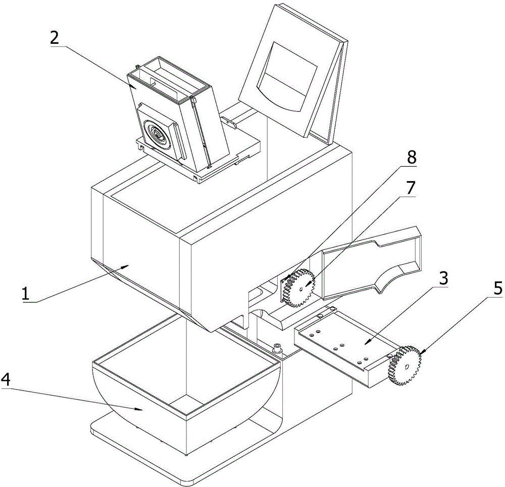
[0041] The fully automatic vegetable cutting machine provided by the present invention comprises a host shell 1, a feeding mechanism 2, a feeding drive transmission mechanism, a cutting mechanism 3 and a vegetable basket 4, such as figure 1 As shown, the host housing 1 has a material outlet, and the feeding mechanism 2 , the feeding drive transmission mechanism and the cutting mechanism 3 are installed in the host housing 1 .

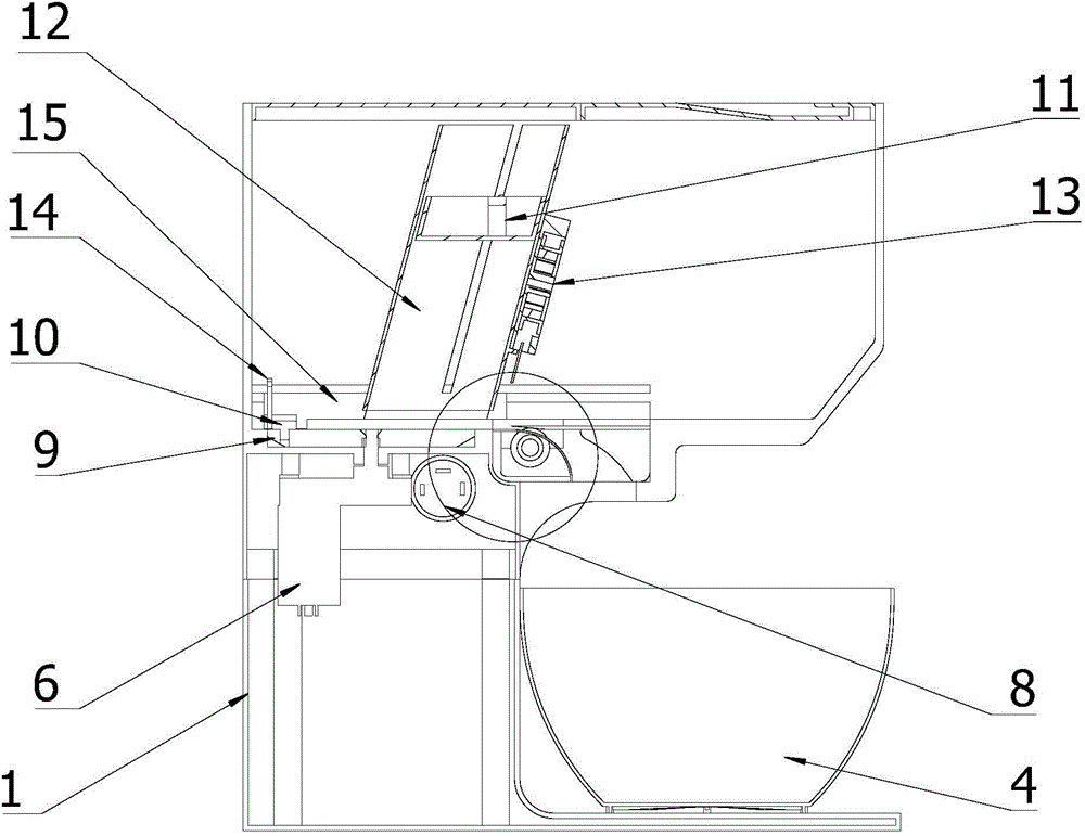
[0042] The feeding drive transmission mechanism includes a first motor 6, a turntable 9, and a cam 10, such as figure 2 , Figure 15 As shown, the output shaft of the first motor 6 is fixedly connected to the center of the turntable 9, and the cam 10 is fixedly mounted on the turntable 9 eccentrically. In this embodiment, the cam 10 is installed at the edge of the turntable 9 away from the center.

[0043] ...