Blow-molding mechanism for handle assembly snapping grooves in container with handle

A mold mechanism and handle technology, which is applied in the field of blow molding mechanism, can solve the problems of high wear rate of parts, permanent deformation of spring, failure of reset of stuck mold, etc., and achieve the effect of reducing wear

Active Publication Date: 2015-09-16
JIANGSU NEWAMSTAR PACKAGING MACHINERY
View PDF4 Cites 6 Cited by
  • Summary
  • Abstract
  • Description
  • Claims
  • Application Information

AI Technical Summary

Problems solved by technology

This method has the following disadvantages: If the container’s tightness on the slot mold is greater than the spring force during the forming process, the slot mold cannot be reset; after long-term use, the spring will undergo permanent deformation, and the elastic force will not reach the original design Requirements: The piston drives the upper and lower two slotted molds through sliding friction, and the wear rate of the parts is relatively high

Method used


Image

  • Blow-molding mechanism for handle assembly snapping grooves in container with handle
  • Blow-molding mechanism for handle assembly snapping grooves in container with handle
  • Blow-molding mechanism for handle assembly snapping grooves in container with handle

Examples


Embodiment Construction

[0022] The technical solution of the present invention will be further described below in conjunction with the accompanying drawings.

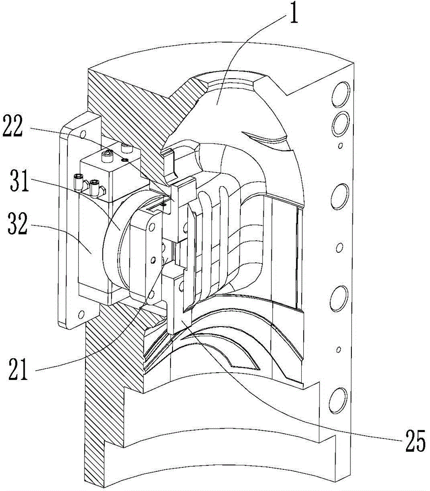
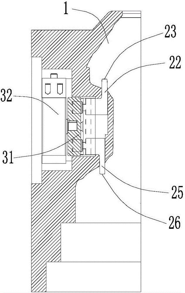
[0023] see Figure 1-3 As shown, the above-mentioned blow molding mechanism for assembling the handle on the container with a handle is set on the frame, and is used to form two upper and lower parts in the blowing mold 1 when the bottle blowing machine blows the container. Card slot molds for blown card slots.

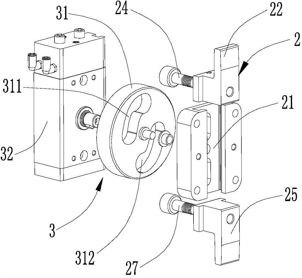
[0024] The above-mentioned blow molding mechanism includes a sliding mold mechanism 2 arranged on the frame for forming the groove mold, and a driving mechanism 3 for driving the mold mechanism 2 to slide on the frame.

[0025] The above-mentioned mold mechanism 2 includes a chute 21 fixed on the frame and distributed along the vertical direction, and a first slot 23 which is provided in the chute 21 and is used to be blown in the blowing mold 1 and slides up and down. The first sliding block 22, the second sliding block 25 ...


PUM


Abstract

The invention discloses a blow-molding mechanism for handle assembly snapping grooves in a container with a handle. The blow-molding mechanism is arranged on a machine frame and is used for forming a snapping groove mold for blow-molding the snapping grooves in a bottle blowing mold when the container is subjected to blow-molding by a bottle blowing machine; the blow-molding mechanism comprises a mold mechanism and a driving mechanism, wherein the mold mechanism is slidably arranged on the machine frame, and the driving mechanism is arranged on the machine frame and is used for driving the mold mechanism to extend into the bottle blowing mold so as to form the snapping groove mold; the driving mechanism is also used for driving the mold mechanism to slide out of blow-molded containers. According to the blow-molding mechanism for the handle assembly snapping grooves in the container with the handle, disclosed by the invention, an oscillating cylinder is arranged to drive a cam to rotate, and the cam drives two sliding blocks to be close to each other or far away from each other, so that the problem that the sliding blocks cannot reset is avoided; the original sliding friction is changed into rolling friction, so that the wear among parts is effectively reduced; the oscillating cylinder is driven through low-pressure gas, so that the blow-molding mechanism is more energy-saving.

Description

technical field [0001] The invention relates to a blow-molding mechanism for a handle fitting slot on a container with a handle. Background technique [0002] In the blowing process of containers with handles, it is necessary to realize the reciprocating movement of the upper and lower handle slot molds through a mechanical mechanism, and the slot molds are generally made into a slider shape. When the container is blown, the slotted mold extends into the blowing mold, and the slotted mold retracts after the bottle blowing is completed, so that the container can be taken out from the blowing mold. [0003] The existing blow molding method generally uses high-pressure gas to make the piston push the upper and lower two slotted molds into the blowing mold for blowing. After the bottle blowing is completed, the piston and the slotted mold are reset by a spring. This method has the following disadvantages: If the container’s tightness on the slot mold is greater than the spring ...

Claims


Application Information

Patent Timeline
Patent Type & Authority Applications(China)
IPC IPC(8): B29C49/32B29C49/48B29L22/00
Inventor 吴贇庞颖楚
Owner JIANGSU NEWAMSTAR PACKAGING MACHINERY
Why Eureka
Try Eureka