Cement bag breaker for construction work

A technology of building construction and bag breaking machine, which is applied in loading/unloading, packaging, cutting and unsealing, etc., which can solve troublesome problems and achieve the effect of convenient collection and processing

Inactive Publication Date: 2020-08-14
安徽筑恒建设有限公司
View PDF7 Cites 9 Cited by
  • Summary
  • Abstract
  • Description
  • Claims
  • Application Information

AI Technical Summary

Problems solved by technology

[0005] In order to overcome the disadvantages that people need to manually cut a hole in the cement bag, it is troublesome, and it is necessary to use a shovel to shovel the cement out for use. After a long time, it is more laborious. The technical problem to be solved is to provide a convenient Cut a hole in the cement bag, and it can also make the cement fall into the collection container, which is a relatively labor-saving cement bag breaker for construction

Method used


Image

  • Cement bag breaker for construction work
  • Cement bag breaker for construction work
  • Cement bag breaker for construction work

Examples


Embodiment 1

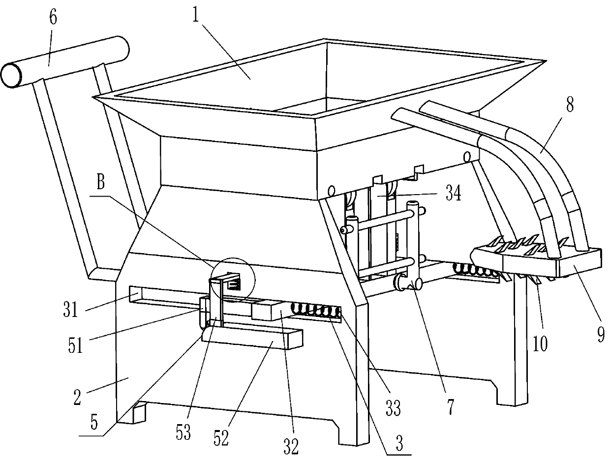
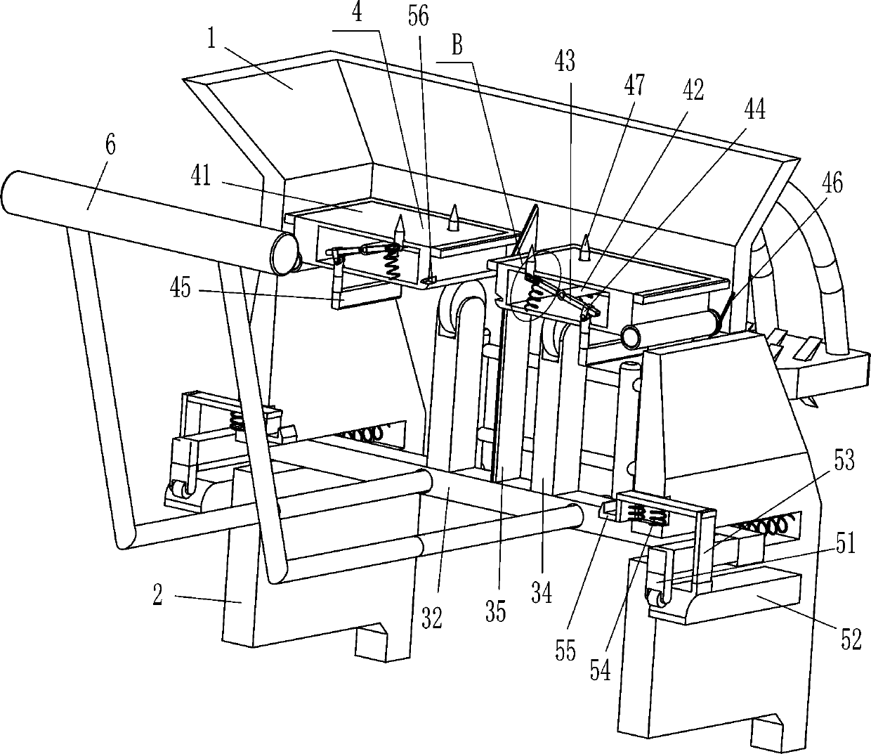
[0023] see Figure 1-Figure 3 , a cement bag breaking machine for building construction, comprising a placement frame 1, a support plate 2, a support cutting mechanism 3 and a swing mechanism 4, the support plate 2 is fixedly connected to the front and rear sides of the bottom of the placement frame 1, and the front and rear support plates A support cutting mechanism 3 is arranged between the two, and a swing mechanism 4 for placing the cement bag is provided in the placing frame 1, and the swing mechanism 4 contacts and cooperates with the support cutting mechanism 3.

[0024] Support cutting mechanism 3 comprises slide plate 32, first spring 33, support wheel 34 and cutter 35, all has chute 31 in the middle part of support plate 2 of front and rear sides, between the chute 31 of front and back sides, sliding type is provided with Sliding plate 32, the front and rear sides on the right side of sliding plate 32 are respectively connected with the first spring 33 between the fr...

Embodiment 2

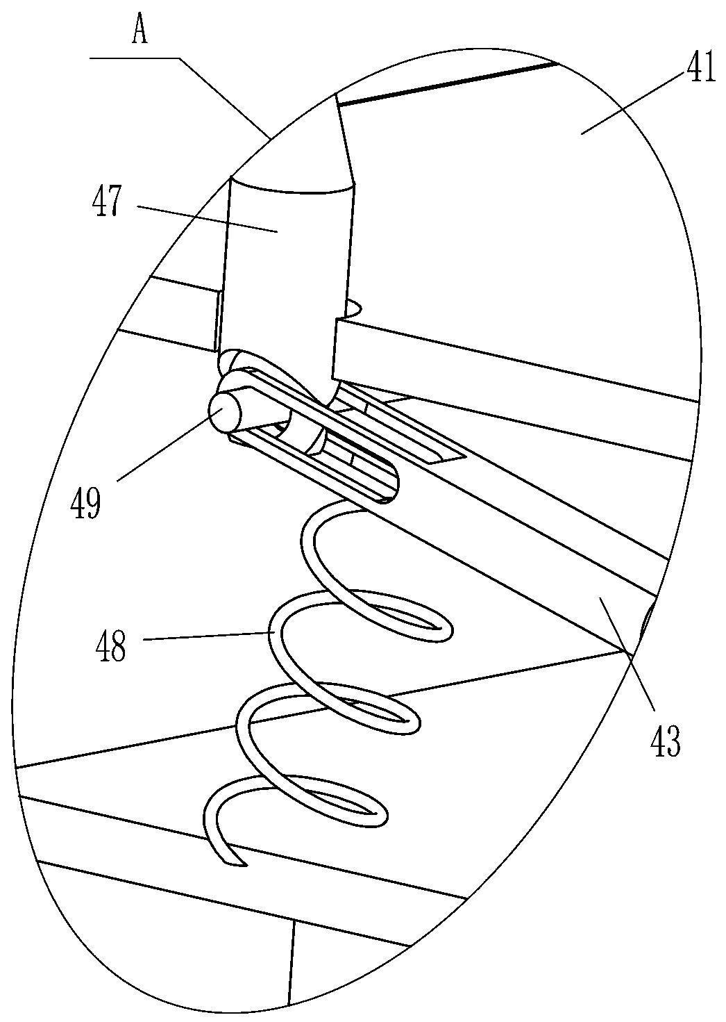
[0030] see figure 1 , figure 2 with Figure 4 Compared with Embodiment 1, the main difference of this embodiment is that in this embodiment, a clamping mechanism 5 is also included, and the clamping mechanism 5 includes a contact wheel 51, a trigger block 52, an L-shaped plate 53, a third spring 54 and Buckle 55, the upper side of the middle part of the support plate 2 on the front and rear sides is slidingly provided with an L-shaped plate 53, and two third springs 54 are connected between the inner top of the L-shaped plate 53 and the inside of the support plate 2, and the L-shaped plate 53 The bottom end is fixedly connected with a trigger block 52, the upper left side of the trigger block 52 is an arc surface, the inner ends of the L-shaped plates 53 on the front and rear sides are fixedly connected with buckles 55, and the front side hollow frame 41 is connected to the middle part of the outer rear side and the rear side hollow frame. The middle part of the outer front...

Embodiment 3

[0033] see figure 1 with figure 2 The main difference between this embodiment and embodiment 1 and embodiment 2 is that in this embodiment, an L-shaped tie rod 6 and a fixed frame 7 are also included, and an L-shaped tie rod is provided for sliding between the front and rear parts of the sliding plate 32. 6. Between the two ends on the right side of the L-shaped pull rod 6, there is a fixed frame 7 that can push the cement bag.

[0034] Also includes arc rod 8, fixed plate 9 and limit block 10, two arc rods 8 are affixed to the upper side of the middle part of the outer right side of the placement frame 1, and two arc rods 8 bottom ends are affixed with The fixed plate 9 that can make cement bag place, fixed plate 9 tops and the bottom all evenly spaced are affixed with the spacer block 10 that can cement bag be fixed.

[0035] When a bag of cement was put into the placement frame 1, the operator could pull the L-shaped pull rod 6 to drive the slide plate 32 to move to the ...


PUM


Abstract

The invention relates to a cement bag breaker, in particular to a cement bag breaker for construction work, and aims to solve the technical problem of designing the labor-saving cement bag breaker forconstruction work, through which people can cut a cement bag to form an opening and cement can drop into a collecting container. The bag breaker for construction work comprises a placing frame, and asupport cutting mechanism, wherein support plates are fixedly connected to one side of the placing frame symmetrically, and the support cutting mechanism is mounted between the two support plates, and used for cutting the cement bag. One cement bag is placed in the placing frame to be in contact with a hollow frame, a sliding plate is pulled to move to the left so that a cutting knife is used forcutting the cement bag to form an opening, when support wheels are divorced from the hollow frame, the hollow frame can drive the cement bag to move downwards, cement can totally drop into the collecting container, the operation of manually cutting the cement bag to form an opening by people is avoided, the cement bag breaker is convenient and effortless, and the condition that a shovel is used for scooping the cement for use, can be avoided.

Description

technical field [0001] The invention relates to a cement bag breaking machine, in particular to a cement bag breaking machine for building construction. Background technique [0002] Cement: powdery hydraulic inorganic gelling material. After adding water and stirring, it becomes a slurry, which can be hardened in air or in water, and can firmly bind sand, stone and other materials together. In the early years the mixture of lime and volcanic ash is very similar to lime pozzolanic cement, use it to glue concrete which made of crushed stone. After hardening, the cement not only has high strength, but also can resist the erosion of fresh water or salt water. For a long time, as an important cementing material, it has been widely used in civil engineering, water conservancy, national defense and other projects. When cement is produced, it is packed in cement bags and transported to designated locations for use. [0003] Existing kerf, such as the Chinese patent with the paten...

Claims


Application Information

Patent Timeline
Patent Type & Authority Applications(China)
IPC IPC(8): B65B69/00B65G65/40B65G69/00
CPCB65B69/0033B65G65/40B65G69/00
Inventor 张财深
Owner 安徽筑恒建设有限公司
Why Eureka
Try Eureka