Rope rolling rack, mountable and demountable gantry crane, and loading and unloading method

A technology for installing gantry cranes and rope roll racks, which is used in transportation and packaging, trolley cranes, load hanging components, etc., can solve the problems of short service life of rope roll racks, large frame moment and difficulty, and save energy. , The rising and falling process is stable and the effect of reducing wear and tear

Inactive Publication Date: 2015-09-16
CHANGSHA LUXI ELECTROMECHANICAL EQUIP ENG
View PDF7 Cites 2 Cited by
  • Summary
  • Abstract
  • Description
  • Claims
  • Application Information

AI Technical Summary

Problems solved by technology

[0002] At present, the hoisting of objects in engineering construction is generally carried out by gantry cranes. Because the frames are fixed together and cannot be disassembled, and the frames are large, road transportation is inconvenient and does not comply with traffic regulations. It is very difficult to carry elbows everywhere. Adapt to multi-site operations in the field
[0003] Existing rope roller frames generally include a frame body and rollers installed at the bottom of the frame body. During the working process, the verticality of the steel rope between the roller and the hoisting box cannot be guaranteed, so that the steel rope rubs against the edge of the bottom plate hole of the hoisting box, and the steel rope is easy to move. Damaged, the roller always plays the role of a fixed pulley and cannot shrink, the frame body bears a large moment, and the service life of the rope roller frame is not long

Method used


Image

  • Rope rolling rack, mountable and demountable gantry crane, and loading and unloading method
  • Rope rolling rack, mountable and demountable gantry crane, and loading and unloading method
  • Rope rolling rack, mountable and demountable gantry crane, and loading and unloading method

Examples


Embodiment 2

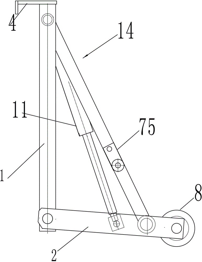
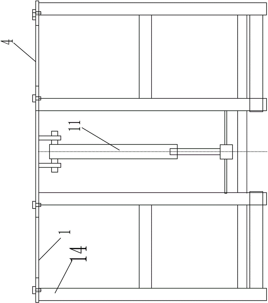
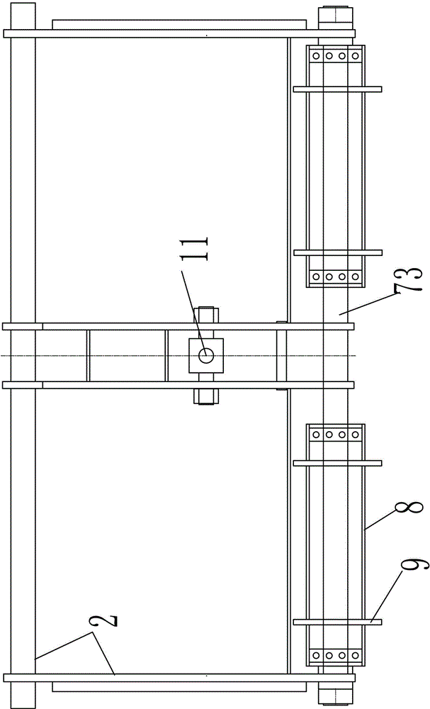
[0087] A rope roller frame, such as Figure 4-5 As shown, it includes a bottom frame 2 and a stand 1 mounted on the bottom frame 2; the top of the stand 1 is provided with a hook horizontal side 4, and one end of the bottom frame 2 is equipped with a rotating shaft 73, which is set on the rotating shaft 73 There is a drum 8 with a retaining rope ring 9; the underframe 2 is fixedly connected with the stand 1, and a horizontal telescopic oil cylinder 11 and a telescopic sleeve 71 are arranged between the underframe 2 and the rotating shaft 73. The bottom frame 2 is provided with a travel switch that triggers the movement of the telescopic oil cylinder 11 . Both sides of the telescopic oil cylinder 11 are provided with telescopic sleeves 71 connecting the underframe 2 and the rotating shaft 73 as auxiliary support members; the telescopic sleeves 71 are provided with stoppers.


PUM


Abstract

The utility model discloses a rope rolling rack and a detachable portal crane. The detachable portal crane comprises a three-dimensional frame formed by detachably connecting multiple blocks together, a traveling crane arranged on the upper part of the three-dimensional frame, and a loading and unloading device used for loading and unloading materials, and also comprises a rope rolling rack arranged at the bottom of the three-dimensional frame, a rope arrangement wheel component arranged on the top of the three-dimensional frame, first traction equipment, second traction equipment and a driving device which drives the traveling crane to reciprocate, wherein the second traction equipment is connected with one end of the loading and unloading device through a second traction rope; the loading and unloading device comprises a movable door; an inner wall of the movable door is connected with the first traction equipment through a first traction rope; the traveling crane comprises a lifting beam and a lifting box arranged on the lifting beam; and an insertion structure for fastening and loosening the loading and unloading device is formed in the lifting box. The portal crane disclosed by the utility model can be detached and moved at any time, is suitable for field operation and contributes to transportation of mechanical equipment.

Description

technical field [0001] The invention relates to the field of mobile cranes, in particular to a rope roller frame, a foldable gantry crane and a method for loading and unloading materials. Background technique [0002] At present, the hoisting of objects in engineering construction is generally carried out by gantry cranes. Because the frames are fixed together and cannot be disassembled, and the frames are large, road transportation is inconvenient and does not comply with traffic regulations. It is very difficult to carry elbows everywhere. Adapt to multi-site operations in the field. [0003] Existing rope roller frames generally include a frame body and rollers installed at the bottom of the frame body. During the working process, the verticality of the steel rope between the roller and the hoisting box cannot be guaranteed, so that the steel rope rubs against the edge of the bottom plate hole of the hoisting box, and the steel rope is easy to move. If it is damaged, the...

Claims


Application Information

Patent Timeline
Patent Type & Authority Applications(China)
IPC IPC(8): B66C13/00B66C19/02
CPCB66C13/00B66C19/02
Inventor 向维
Owner CHANGSHA LUXI ELECTROMECHANICAL EQUIP ENG
Why Eureka
Try Eureka