Draught fan impeller and blade skeleton line fitting method thereof as well as draught fan

A technology for fan impellers and blades, applied in machines/engines, mechanical equipment, liquid fuel engines, etc., can solve problems such as the influence of fan aerodynamic performance and noise level, large pressure gradient at the blade outlet, and outlet airflow separation, etc. Efficiency, reducing pressure gradient, suppressing the effect of gas flow separation

Active Publication Date: 2015-09-16
GREE ELECTRIC APPLIANCES INC
View PDF5 Cites 5 Cited by
  • Summary
  • Abstract
  • Description
  • Claims
  • Application Information

AI Technical Summary

Problems solved by technology

However, for the fan with the above-mentioned blades, the air flow is more likely to form a shedding vortex at the blade outlet section, resulting in an increase in local velocity and a low-pressure area, which makes it easier to generate a large pressure gradient at the blade outlet, resulting in a greater possibility of separation of the outlet airflow. It has a great influence on the aerodynamic performance and noise level of the fan

Method used


Image

  • Draught fan impeller and blade skeleton line fitting method thereof as well as draught fan
  • Draught fan impeller and blade skeleton line fitting method thereof as well as draught fan
  • Draught fan impeller and blade skeleton line fitting method thereof as well as draught fan

Examples


Embodiment Construction

[0048] The following will clearly and completely describe the technical solutions in the embodiments of the present invention with reference to the accompanying drawings in the embodiments of the present invention. Obviously, the described embodiments are only some, not all, embodiments of the present invention. Based on the embodiments of the present invention, all other embodiments obtained by persons of ordinary skill in the art without making creative efforts belong to the protection scope of the present invention.

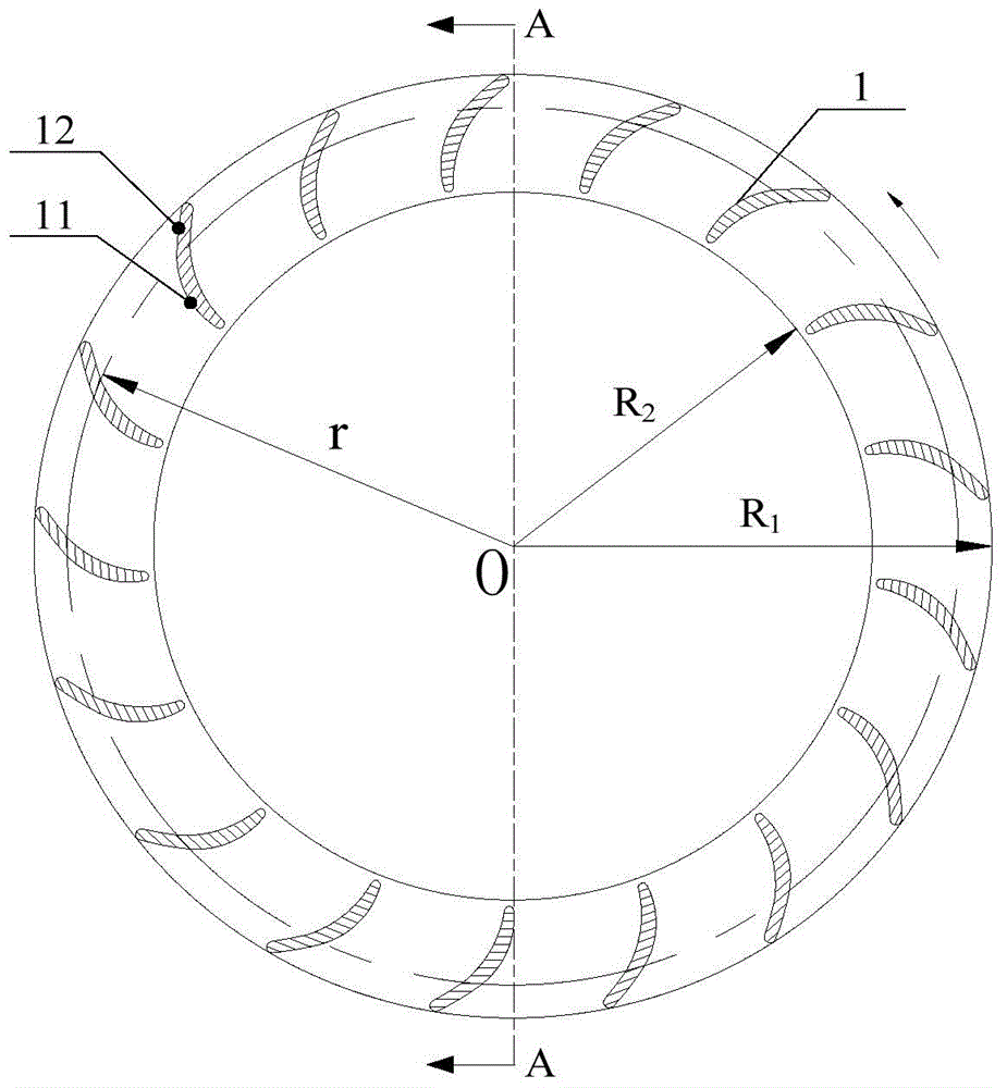
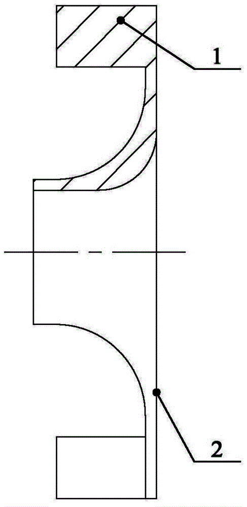
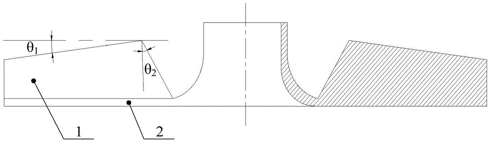
[0049] Please refer to the attached Figure 1-6 , The fan impeller provided by the embodiment of the present invention includes: a rear disk 2 , and blades 1 arranged on the rear disk 2 . Wherein, the blade 1 includes a connected blade inlet section 11 and a blade outlet section 12, the blade inlet section 11 and the blade outlet section 12 are distributed sequentially along the length direction of the blade 1, the blade inlet section 11 is close to the centra...


PUM


Abstract

The invention discloses a draught fan impeller and a blade skeleton line fitting method thereof as well as a draught fan. The draught fan impeller comprises a rear disc and a blade arranged on the rear disc, wherein the blade comprises a blade inlet section and a blade outlet section which are connected; the blade inlet section and the blade outlet section are sequentially distributed along the length direction of the blade; the blade inlet section is close to the central axis of the rear disc; the blade inlet section is in a wing-shaped structure; the blade outlet section is in an equal-circular-rector flow type structure. According to the draught fan impeller disclosed by the invention, the blade outlet section is designed into the equal-circular-rector flow type structure, and a momentum moment at the blade outlet section along the meridian plane of the draught fan impeller keeps constant, so that the pressure gradient of airflow at the blade outlet section is effectively reduced, the airflow separation at the blade outlet section is inhibited, and the influences on the aerodynamic performances and the noise levels by the draught fan are reduced.

Description

technical field [0001] The invention relates to the technical field of fan impellers, and more specifically, to a fan impeller, a blade bone line fitting method thereof, and a fan. Background technique [0002] At present, the fan impeller mainly adopts straight blades and arc airfoil blades to facilitate mold opening and processing. However, for the fan with the above-mentioned blades, the air flow is more likely to form a shedding vortex at the blade outlet section, resulting in an increase in local velocity and a low-pressure area, which makes it easier to generate a large pressure gradient at the blade outlet, resulting in a greater possibility of separation of the outlet airflow. It has a great influence on the aerodynamic performance and noise level of the fan. [0003] To sum up, how to suppress the separation of the air flow at the outlet of the blades so as to reduce the impact on the aerodynamic performance and noise level of the fan is an urgent problem to be sol...

Claims


Application Information

Patent Timeline
Patent Type & Authority Applications(China)
IPC IPC(8): F04D29/30F04D29/66
Inventor 廖俊杰刘池彭勃熊军罗永前
Owner GREE ELECTRIC APPLIANCES INC
Why Eureka
Try Eureka