External device of mobile terminal
A technology of mobile terminal and external device, applied in the field of wireless communication, can solve the problems of high replacement cost and lack of NFC-SWP function, and achieve the effect of reducing application cost
- Summary
- Abstract
- Description
- Claims
- Application Information
AI Technical Summary
Problems solved by technology
Method used
Image

Examples
Embodiment 1
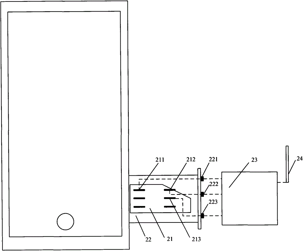
[0017] Embodiment 1, in order to solve the above-mentioned NFC chip and the pin connection problem of SIM card, in specific implementation, the inventor considers that the SIM card holder of mobile terminal (such as Iphone5) needs to be improved, as figure 2 As shown, the external device of the mobile terminal in this embodiment includes: the SIM card 21 that can carry the mobile terminal and the SIM card holder 22 that can be inserted into the SIM card slot of the mobile terminal, the NFC chip 23 and the NFC antenna 24; The card tray 22 leads the C1 pin 211, the C5 pin 212 and the C6 pin 213 of the mobile terminal SIM card 21 to the outer wall of the SIM card tray 22, and forms three corresponding internal contacts respectively 221, 222, 223, that is, the C1 pin 211 corresponds to the internal contact 221, the C5 pin 212 corresponds to the internal contact 222, and the C6 pin 213 corresponds to the internal contact 223; the C1 pin 211, the C5 pin 212 and the C6 pin 213 pass t...
Embodiment 2
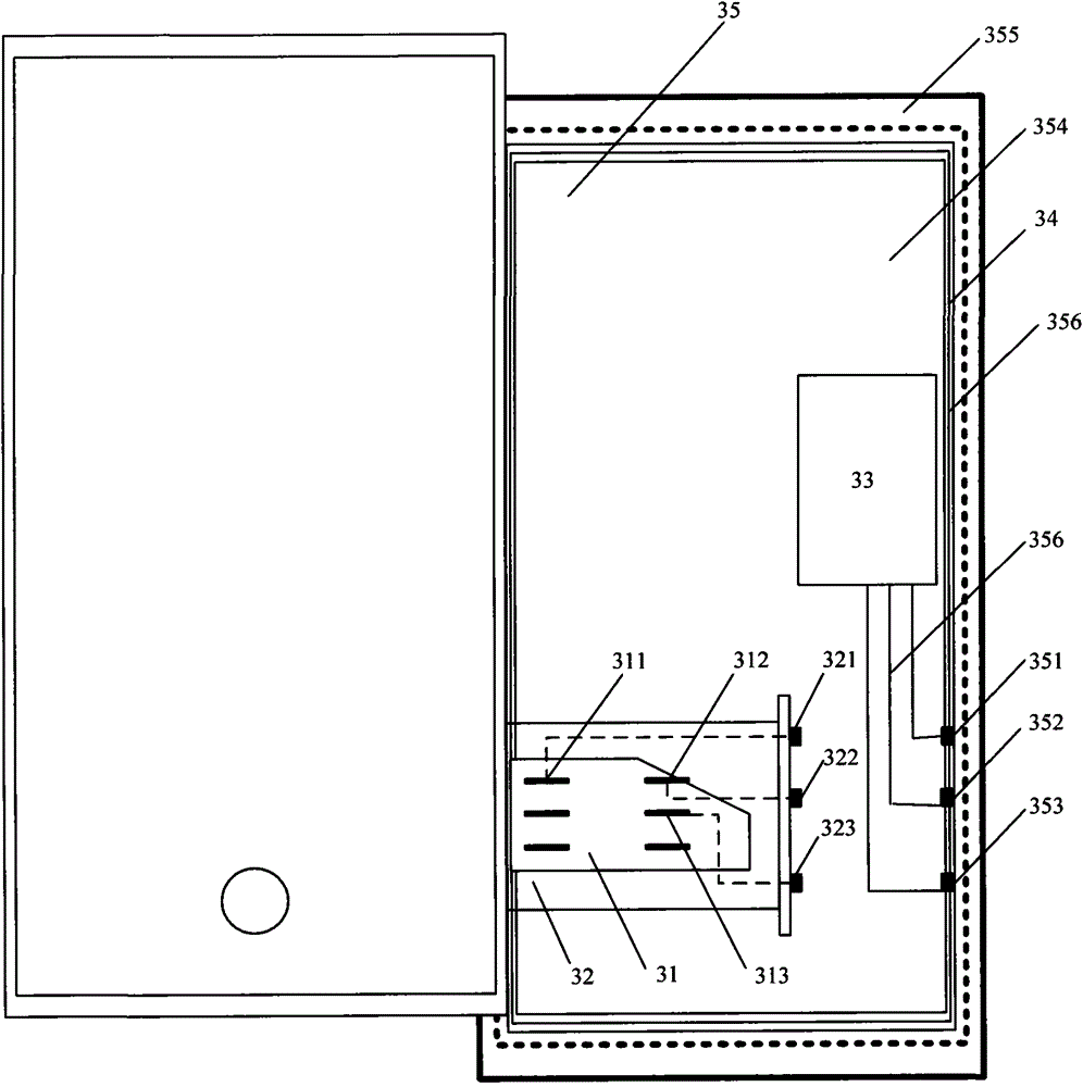
[0018] Embodiment 2, in order to facilitate the pin connection of the NFC chip and the SIM card, see image 3 As shown, this embodiment is optimized on the basis of Embodiment 1, including: a SIM card holder 32 that can carry a SIM card 31 of a mobile terminal and can be inserted into the SIM card slot of the mobile terminal, an NFC chip 33 and an NFC Antenna 34; wherein, the NFC chip 33 and the NFC antenna 34 are integrated on the housing 35 matched with the mobile terminal, and the housing 35 is also provided with 3 external contacts connected to the NFC chip 33, respectively 351, 352, 353. The SIM card holder 32 leads the C1 pin 311, the C5 pin 312 and the C6 pin 313 of the mobile terminal SIM card 31 to the outer wall of the SIM card holder 32, and forms three corresponding internal contacts respectively 321, 322 , 323 , that is, the C1 pin 311 corresponds to the internal contact 321 , the C5 pin 312 corresponds to the internal contact 322 , and the C6 pin 313 corresponds ...
PUM
 Abstract
Description
Claims
Application Information
PatSnap Eureka turns technology decisions into work you can execute. Powered by our Innovation Knowledge Graph, it runs expert workflows across engineering, life sciences, materials and intellectual property. Get your review-ready output in minutes.


