Method of depositing an oxidation and fatigue resistant MCrAIY-coating

a technology of oxidation and fatigue resistance, applied in the direction of superimposed coating process, machines/engines, mechanical equipment, etc., can solve the problems of .gamma/.gamma, failure of components, and common incidence of corrosion, so as to increase the tmf life of the coating, reduce the cost of the coating application by electroplating process, and reduce the effect of oxygen impurities

Inactive Publication Date: 2004-04-29
ALSTOM (SWITZERLAND) LTD
View PDF44 Cites 34 Cited by
  • Summary
  • Abstract
  • Description
  • Claims
  • Application Information

AI Technical Summary

Benefits of technology

0013] It is noted that the cost of the application of a coating by an electroplated process is considerably lower than by a conventional plasma spray coating. In addition, the electroplated process has a thickness control of .+-.20 .mu.m or better, whereas conventional plasma spray coating processes have thickness scatters of .+-.75 .mu.m or even more. Thus, a coating with a layer thickness in a range of 25-400 .mu.m can be applied. A thinner coating increase the TMF life of the coating. The used electroplated process has no line of sight limitation and can coat complex contour surfaces without any difficulty. In addition the coating thus manufactured contains very little oxygen impurity. The deposited coating is heat-treated in vacuum, argon, hydrogen at 1140.degree. C. for 2 to 12 hours.
0014] An addition of (wt.-%) 0.01 to 3% Fe is provided for increased ductility. An addition of (wt.-%) 0.5-2.5% Si, 0.2-1.5% Hf, 0.01-0.2% Zr or 0-2% Ta either alone or in combination for increased scale adhesion of the deposited coating.

Problems solved by technology

One major disadvantage of .gamma. / .gamma.
'-type of MCrAlY coatings is that due to the low aluminum content they do not form a continuous alumina film at temperatures below 1000.degree. C. what leads to a problem with the bonding adherence with the TBC.
Further, in advanced turbine engines, incidences of corrosion are not common due to higher engine operating temperature and use of cleaner fuels.
Since the substrate is not oxidation resistant the advancing oxygen (through the cracks) causes the oxidation of the underlying substrate and triggers the failure of the components.
The problem is then to find a method that allows a deposition of thin protective coatings on complex turbine airfoils.
However, there are limitations of these processes; a) difficult or unable to deposit a thin coating uniformly, b) poor thickness control and c) a line of sight limitation.
Since airfoils contain many complex contoured surface i.e. airfoil to platform transition area, leading edge etc., the line of sight limitation present a difficulty in getting a good uniform coverage of coatings with microstructural integrity.
It is noted that the cost of the application of a coating by an electroplated process is considerably lower than by a conventional plasma spray coating.

Method used


Image

  • Method of depositing an oxidation and fatigue resistant MCrAIY-coating
  • Method of depositing an oxidation and fatigue resistant MCrAIY-coating

Examples


Embodiment Construction

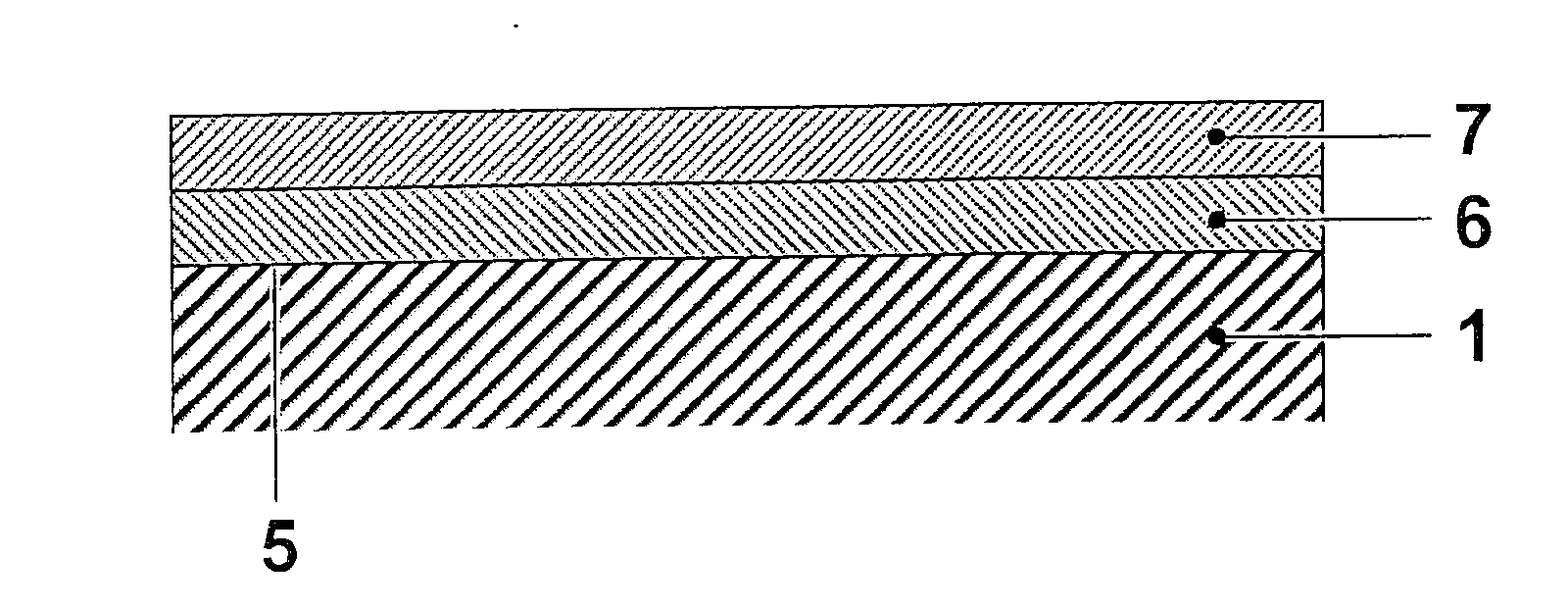
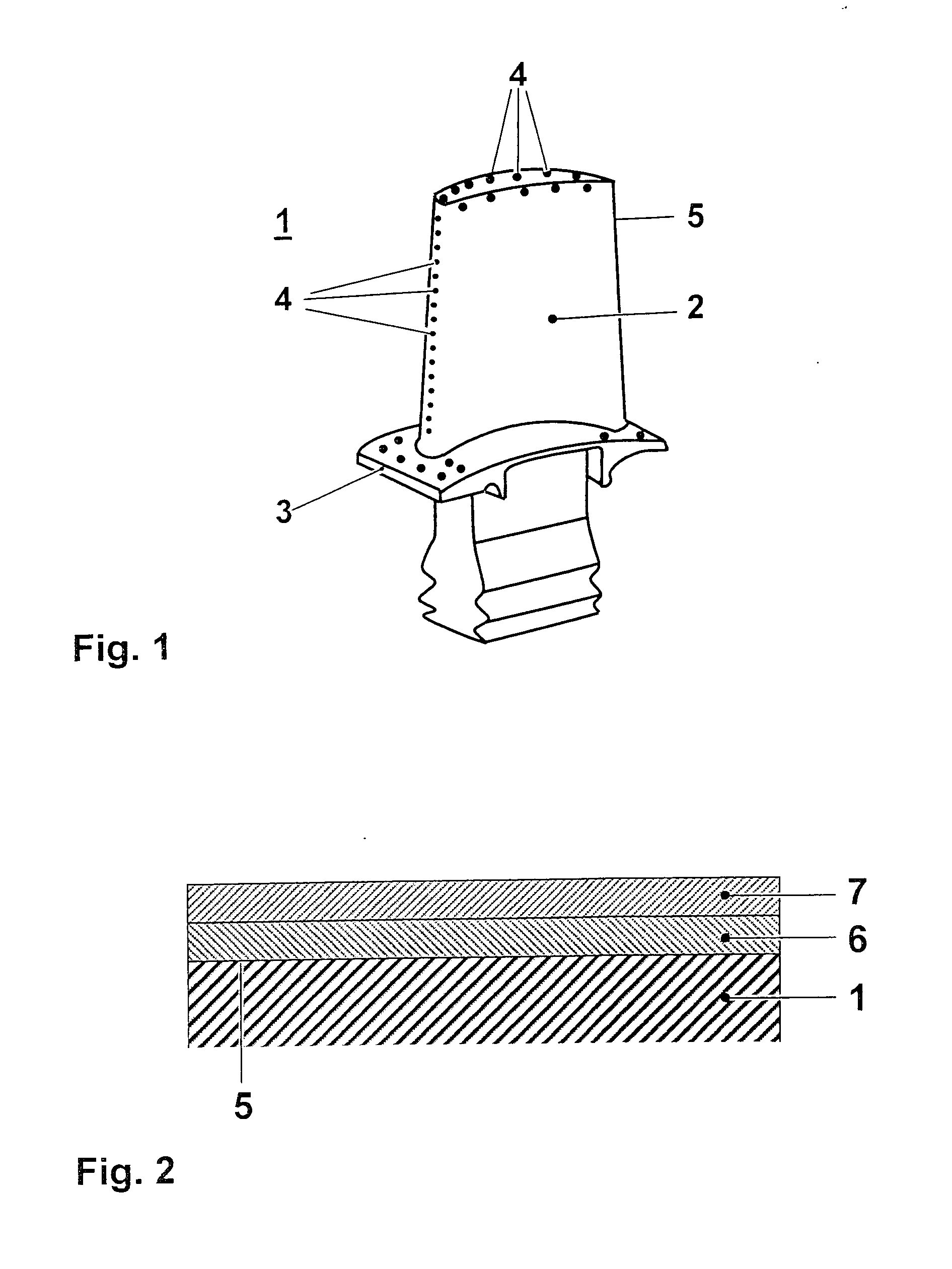
[0020] The present invention is generally applicable to components that operate within environments characterised by relatively high temperature, and are therefore subjected to severe thermal stresses and thermal cycling. Notable examples of such components include the high and low pressure nozzles and blades, shrouds, combustor liners and augmentor hardware of gas turbine engines. FIG. 1 shows as an example such an article 1 as blades or vanes comprising a blade 2 against which hot combustion gases are directed during operation of the gas turbine engine, a cavity, not visible in FIG. 1, and cooling holes 4, which are on the external surface 5 of the component 1 as well as on the platform 3 of the component. Through the cooling holes 4 cooling air is ducted during operation of the engine to cool the external surface 5. The external surface 5 is subjected to severe attack by oxidation, corrosion and erosion due to the hot combustion gases. In many cases the article 1 consists of a ni...


PUM

PropertyMeasurementUnit
thicknessaaaaaaaaaa
thicknessaaaaaaaaaa
thicknessaaaaaaaaaa

Abstract

A method of depositing a layer (6) of highly oxidation and fatigue resistant MCrAlY-coating by an electroplated process has been described. A relative thin coating on an industrial gas turbine component was applied with a thickness control of ±20 mum of the thickness of the applied layer (6) on gas turbine articles (1). The said MCrAlY coatings comprise an addition of (wt.-%) 0.01 to 3% Fe. In addition to Fe the MCrAlY coatings may contain 0.5-2.5% Si, 0-1.5% Hf, 0.01-0.2% Zr and 0-2% Ta, alone or in combination.

Description

[0001] This invention relates according to claim 1 to a protection of gas turbine blades and vanes against oxidation and thermal mechanical fatigue by using MCrAlY overlay coatings deposited by an electroplated process.STATE OF THE ART[0002] The turbine blades and vanes designed for use at high temperature are usually coated with environmentally resistant coatings. For example, MCrAlY overlay coatings are used for protection of turbine blades and vanes. MCrAlY protective overlay coatings are widely known in the prior art. They are a family of high temperature coatings, wherein M is selected from one or a combination of iron, nickel and cobalt. As an example U.S. Pat. No. 3,528,861 or U.S. Pat. No. 4,585,481 are disclosing such kind of oxidation resistant coatings. U.S. Pat. No. 4,152,223 as well discloses such method of coating and the coating itself. Besides the .gamma. / .beta.-MCrAlY-coating, there is another class of overlay MCrAlY coatings which are based on a .gamma. / .gamma.'-ga...

Claims


Application Information

Patent Timeline
Patent Type & Authority Applications(United States)
IPC IPC(8): C23C4/18C23C28/00C23C30/00C25D15/02F01D5/28
CPCC22C19/058C23C4/18F01D5/288C23C30/00C25D15/02C23C28/00
Inventor KHAN, ABDUS SUTTARBOSSMANN, HANS-PETERDUDA, THOMASSCHNELL, ALEXANDERSTEFANSSON, KARL-JOHANTOENNES, CHRISTOPH
Owner ALSTOM (SWITZERLAND) LTD
Why Eureka
Try Eureka