Semiconductor devices with core-shell structures

A core structure and shell material technology, applied in semiconductor devices, semiconductor/solid-state device manufacturing, electrical components, etc., can solve problems such as poor subthreshold characteristics, limitations in the miniaturization of planar devices and suitable material selection

Active Publication Date: 2015-09-16
TAIWAN SEMICON MFG CO LTD
View PDF3 Cites 14 Cited by
  • Summary
  • Abstract
  • Description
  • Claims
  • Application Information

AI Technical Summary

Problems solved by technology

[0002] Conventional planar devices often have limitations in terms of miniaturization and selection of suitable materials
As feature dimensions of semiconductor devices continue to

Method used


Image

  • Semiconductor devices with core-shell structures
  • Semiconductor devices with core-shell structures
  • Semiconductor devices with core-shell structures

Examples


Embodiment Construction

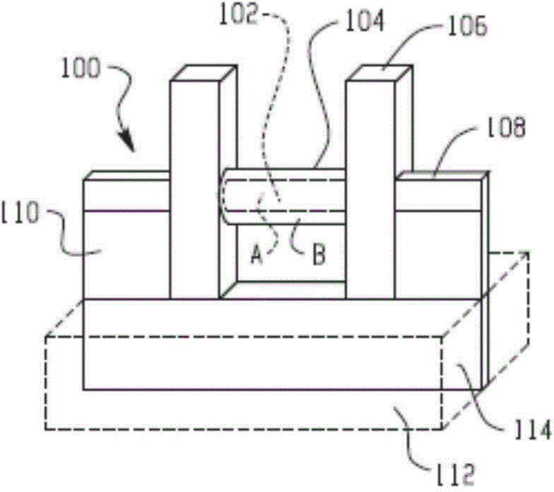
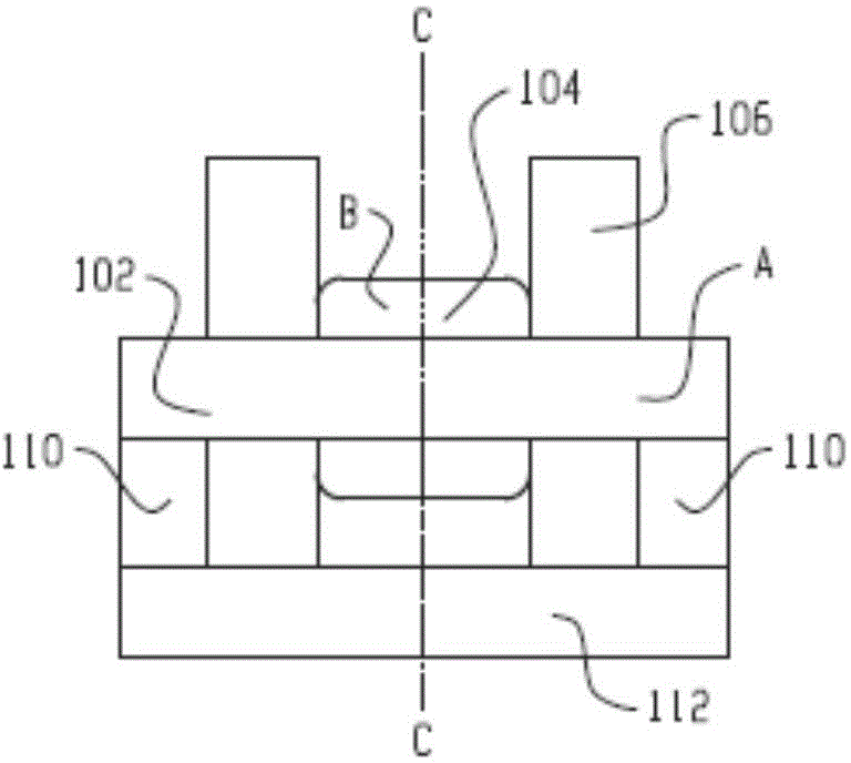
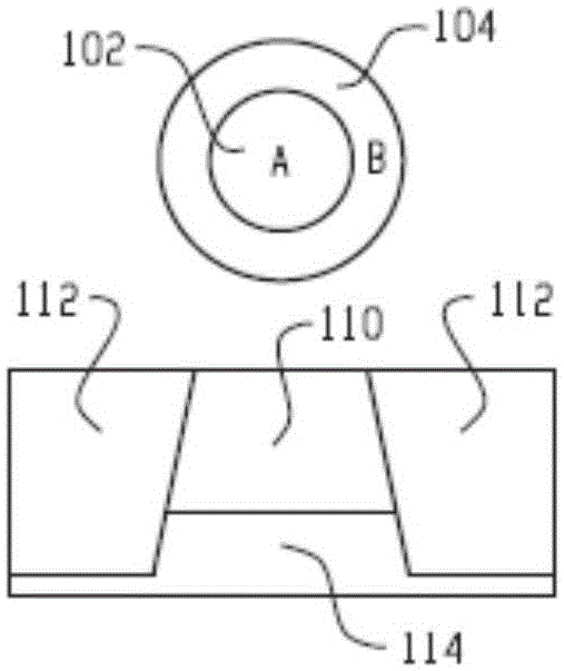
[0033] The following disclosure provides many different embodiments or examples for implementing different features of the present invention. Specific examples of components and arrangements are described below to simplify the invention. Of course, these are only examples and are not intended to limit the invention. For example, in the following description, forming the first member above or on the second member may include an embodiment in which the first member and the second member are formed in direct contact, and may also include that the first member and the second member may be formed between the first member and the second member. An embodiment in which additional components are used so that the first component and the second component may not directly contact. In addition, the present invention may repeat reference numerals and / or characters in multiple examples. This repetition is for the purpose of simplification and clarity, and does not in itself indicate the rel...


PUM


Abstract

A device structure includes: a core structure formed on a support, and a shell material formed on the core structure and surrounding at least part of the core structure. The shell material and the core structure are configured to form a quantum-well channel in the shell material.

Description

Technical field [0001] The technology described in the present invention generally relates to semiconductor devices, and more specifically, to the manufacture of semiconductor devices. Background technique [0002] Traditional planar devices usually have limitations in miniaturization and selection of suitable materials. As the component size of semiconductor devices continues to shrink (for example, into the sub-50nm range), various problems such as short channel effects and poor sub-threshold characteristics usually become more serious in traditional planar devices. New device geometries with enhanced performance (such as three-dimensional device structures (for example, FinFET)) and heterogeneous integration of different high-mobility channels for N-MOS and P-MOS devices have been developed to advance devices and circuits Development towards higher packing density. Summary of the invention [0003] In order to solve the defects in the prior art, the present invention provides...

Claims


Application Information

Patent Timeline
IPC IPC(8): H01L29/775H01L29/78H01L21/335B82Y10/00
CPCH01L21/02538H01L29/165H01L29/66477H01L21/02532H01L29/7842H01L29/125H01L29/205H01L29/0673H01L21/02603H01L29/267H01L29/517H01L29/518H01L29/66431H01L29/775H01L29/7781H01L29/0676B82Y10/00H01L29/068H01L29/42392H01L29/78696H01L29/0669H01L29/7853H01L29/0665Y10S977/938H01L29/66795
Inventor 卡洛斯·H.·迪亚兹林群雄张惠政章勋明王建勋黄懋霖
Owner TAIWAN SEMICON MFG CO LTD
Why Eureka
Try Eureka