
Strain gauge automatic welding and pasting device

A sticking device and automatic welding technology, applied in the direction of connection, connecting components, material gluing, etc., can solve the problems of difficult to control the sticking position, waste of strain gauges, delaying time, etc., to achieve automatic sticking, improve sticking quality, and save sticking time. Effect

Inactive Publication Date: 2015-09-16
CHINA UNIV OF PETROLEUM (EAST CHINA)
View PDF6 Cites 4 Cited by
  • Summary
  • Abstract
  • Description
  • Claims
  • Application Information

AI Technical Summary

Problems solved by technology

However, the sticking of the strain gauges in the process of engineering testing is manually operated by the experimenter, and the sticking quality of the strain gauges depends on the proficiency of the operator.
Due to the complicated manual pasting operation, the pasting position is not easy to control or the pressing is uneven during pasting, which not only leads to waste of strain gauges but also wastes precious time
In addition, the connection between the traditional strain gauge wire and the terminal and between the terminal and the wire is also connected together by manual welding. During the operation, the welding quality depends on the proficiency of the tester, and there is a problem of quality assurance rate. There are also problems of time-consuming and consumables

Method used


Image

  • Strain gauge automatic welding and pasting device
  • Strain gauge automatic welding and pasting device
  • Strain gauge automatic welding and pasting device

Examples


Embodiment Construction

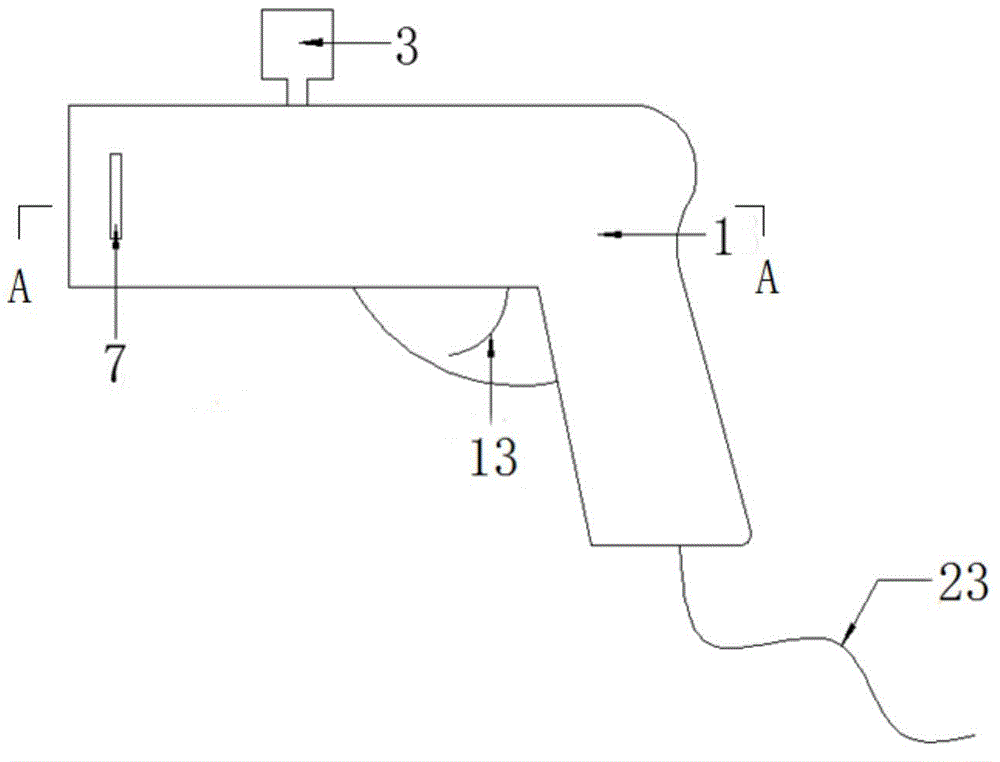
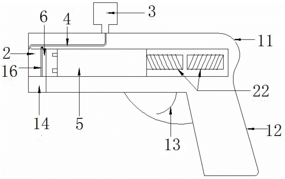
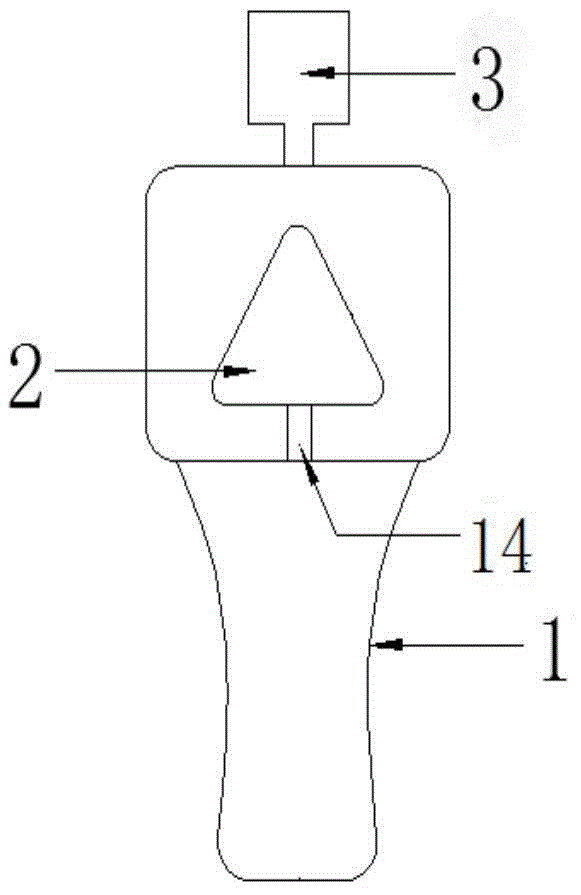
[0016] Such as figure 1 , figure 2 , image 3 As shown, the strain gauge automatic welding and pasting device includes: a gun-shaped main body 1; the gun-shaped main body 1 includes a gun barrel 11, a handle 12 is provided under the rear end of the gun barrel, and a trigger 13 is provided at the intersection of the top of the front side of the handle 12 and the gun barrel ; The gun barrel 11 is provided with a smoothbore 2, the smoothbore 2 extends from the gun barrel front end to the rear end but does not penetrate the rear end, and the cross section of the smoothbore 2 is a triangle; Rod 5, carrier 6, curled welding baffle 16; a carrier hole 7 is provided on one side of the front end of the gun barrel 11, and the carrier hole 7 vertically runs through the smooth bore 2, and the bottom of the gun barrel 11 extends backward from the front end with a wiring chute 14, the bottom wall through which the wiring chute 14 penetrates.

[0017] Such as figure 2 , Figure 4 As sh...


PUM


Abstract

The invention belongs to the field of engineering tests, and in particular relates to a strain gauge automatic welding and pasting device. The strain gauge automatic welding and pasting device comprises a gun-shaped main body, wherein the gun-shaped main body comprises a gun barrel, a handle is arranged under the rear end of the gun barrel, and a trigger is arranged at a joint of the front side top part of the handle and the gun barrel; a smoothbore is arranged inside the gun barrel, the smoothbore extends from the front end to the rear end of the gun barrel but does not penetrate the rear end, and the cross section of the smoothbore is a triangle; an electromagnetic power device, an extruding rod, a carrier and a curly welding baffle plate are arranged in the smoothbore from back to front in sequence; and a carrier hole groove is formed in one side of the front end of the gun barrel, the carrier hole groove penetrates the smoothbore vertically, a wiring sliding groove extends from the front end to the rear end of the bottom part of the gun barrel, and the wiring sliding groove penetrates the bottom wall. The strain gauge automatic welding and pasting device provided by the invention can position the location of a strain gauge accurately, realizes the automatic welding of wiring terminals and automatic pasting of the strain gauge, can effectively improve the pasting quality of the strain gauge, saves pasting time, and can be used by workers with or without manual pasting experience.

Description

technical field [0001] The invention belongs to the field of engineering testing, and in particular relates to an automatic welding and pasting device for strain gauges. Background technique [0002] In engineering testing, in order to test the strain of materials or components, and then obtain the stress of materials or components, strain gauges are often used for measurement. The sticking quality of the strain gauge is a key factor for the success of the experiment. However, the sticking of strain gauges in the process of engineering testing is manually operated by the experimenter, and the sticking quality of strain gauges depends on the proficiency of the operator. Due to the complicated manual pasting operation, the pasting position is difficult to control or the uneven pressing during pasting not only leads to waste of strain gauges but also wastes valuable time. In addition, the connection between the traditional strain gauge wire and the terminal and between the te...

Claims


Application Information

Patent Timeline
Patent Type & Authority Applications(China)
IPC IPC(8): H01R43/02F16B11/00
CPCF16B11/00F16B11/006H01R43/02H01R43/0263
Inventor 康杰刘晓辉孙翔李春宝
Owner CHINA UNIV OF PETROLEUM (EAST CHINA)
Learn More