Trap type particle capturing apparatus and power transmission and transformation equipment

A technology of power transmission and transformation equipment and capture device, applied in the field of high-voltage power transmission and transformation, can solve problems such as inconvenient implementation, achieve the effects of convenient implementation, avoid insulation breakdown, and reduce the impact of insulation performance

Active Publication Date: 2015-09-16
河南省高压电器研究所有限公司
View PDF6 Cites 6 Cited by
  • Summary
  • Abstract
  • Description
  • Claims
  • Application Information

AI Technical Summary

Benefits of technology

This technology allows for easy installation or replacement of an installed particulate filter system inside a new power transferring transformer unit (PTU). By attaching this special apparatus onto the outside of the PTU's flanged pipe instead of replacing it altogether, costs can be saved while still maintaining its effectiveness over time. Additionally, by allowing certain types of material to pass freely between two different parts within the same part, there will no harm their properties during use. Overall, these technical improvements make sure that the power transmitting and converting units work better at preventing electrical disruptions caused by dust buildup.

Problems solved by technology

This patented technical problem addressed during the development phase for an electricity transformer (PT) machine used in power systems has been related to the accumulated debris that occurs when there's no longer enough space available inside or around them due to factors like temperature variations over time. These deposits may lead to reduced efficiency or even damage to components within the PT machines themselves. To solve these issues, various techniques have emerged such as adding extra parts called grids made from materials like metal wire mesh or plastic foam to prevent any unwanted material from entering through certain openings. However, they also change the design of the original component making up the machine difficult if needed again after being built.

Method used


Image

  • Trap type particle capturing apparatus and power transmission and transformation equipment
  • Trap type particle capturing apparatus and power transmission and transformation equipment

Examples


Embodiment Construction

[0020] Embodiments of the present invention will be further described below in conjunction with the accompanying drawings.

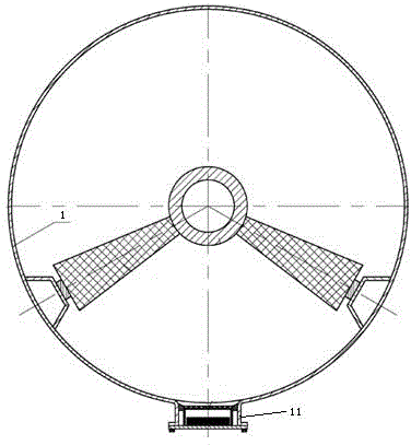
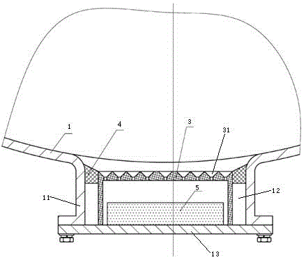
[0021] Specific embodiments of the power transmission and transformation equipment of the present invention, such as Figure 1 to Figure 2 As shown, it includes a cylinder body 1 whose axis extends in the front-rear direction. The bottom of the cylinder body 1 is provided with a flange cylinder 11 , and the flange cylinder 11 is provided with a flange hole 12 and a flange cover 13 for sealing the flange hole 12 . The power transmission and transformation equipment includes a trap-type particle capture device. The trap-type particle capture device includes a guide ring 4 and a trap net 3 fixed in the flange hole 12. The trap net 3 is an inverted cover structure, and the guide ring 4 is set in the On the trap net 3 , the trap net 3 is fixed on the flange cover 13 , the guide ring 4 has a guide surface, and the trap net 3 is provided with a leakage hole 31 ...


PUM


Abstract

The invention relates to the high-voltage power transmission and transformation field, particularly to a trap type particle capturing apparatus and power transmission and transformation equipment. The trap type particle capturing apparatus comprises a guiding ring and trap nets, wherein the guiding ring and the trap nets are fixed in a flange hole formed in the bottom of a power transmission and transformation equipment cylinder. The guiding ring has a guiding surface enabling particles to slide towards the trap nets; and the guiding surface is not lower than the trap nets. Leakage holes for penetration of particles are formed in the trap nets. According to the invention, the particle capturing apparatus is installed in the flange cylinder of the existing power transmission and transformation equipment without changing the cylinder structure and original materials are used, so that the cost is saved and implementation of the apparatus becomes convenient. The particles slide along the guiding surface of the guiding ring and enter the leakage holes of the trap nets, thereby realizing particle capturing, thereby avoiding an insulation breakdown caused by electric field distortion due to the particles and reducing the influence on the insulation performance of the power transmission and transformation equipment by the particles.

Description


Claims


Application Information

Patent Timeline
Owner 河南省高压电器研究所有限公司
Why Eureka
Try Eureka