Laminated common-mode choke coil

Active Publication Date: 2013-06-20
TAIYO YUDEN KK
View PDF7 Cites 23 Cited by
  • Summary
  • Abstract
  • Description
  • Claims
  • Application Information

AI Technical Summary

Benefits of technology

[0009]With a laminated common-mode choke coil using glass ceramics, Ag or Cu can be used for the internal conductors so that the glass ceramic layer and internal conductors can be sintered at the same time. In particular, Ag is a favorable choice for the internal conductors because it ca

Problems solved by technology

However, Ag presents a concern in that it easily diffuses in the glass

Method used


Image

  • Laminated common-mode choke coil
  • Laminated common-mode choke coil
  • Laminated common-mode choke coil

Examples


example

[0049]The present invention is explained more specifically below using an example. It should be noted, however, that the present invention is not at all limited to the embodiments described in this example.

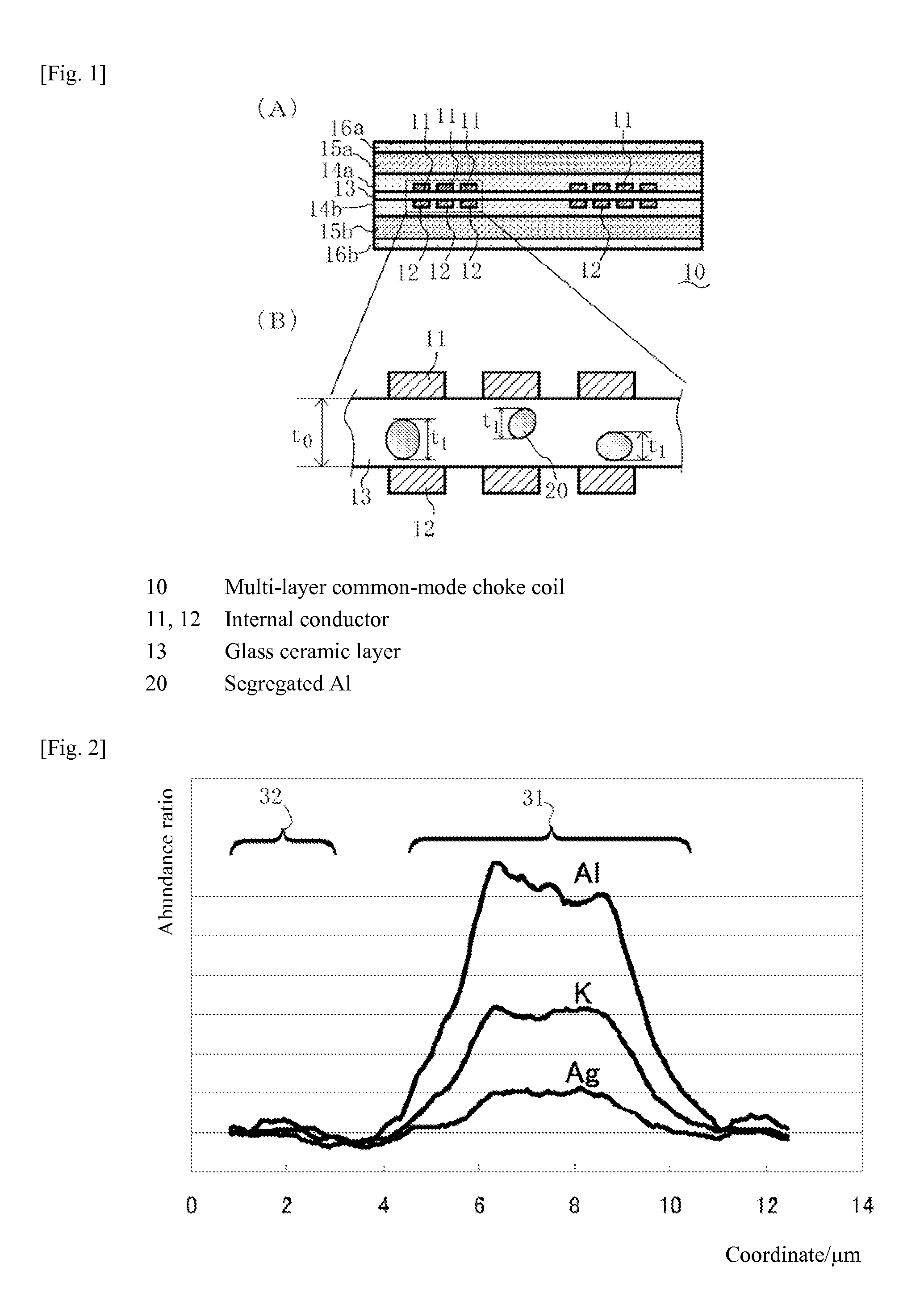
[0050](Material for Glass Ceramic Layer)

[0051]As the material for glass ceramic layer, 75 percent by volume of glass frit, prepared by 77.5 percent by weight of SiO2, 20 percent by weight of B2O3, 2 percent by weight of K2O, and 0.5 percent by weight of Al2O3 in equivalent oxides, and 25 percent by volume of quartz used as filler, were used. The ingredients were crushed to 1.5 μm (value of d50) in a bead mill. ZrO2 balls, Al2O3 balls, etc., can be used as crushing medium, and ZrO2 balls were used in this example. Dispersant was added as necessary. Ethanol, toluene, methyl ethyl ketone, etc., can be used as dispersion medium, for example, and ethanol was used in this example.

[0052](Manufacturing of Green Sheet for Glass Ceramic Layer)

[0053]A slurry was obtained by mixing and kneadi...


PUM


Abstract

A laminated common-mode choke coil offering higher insulation reliability has a glass ceramic layer, two spiral internal conductors facing each other and sandwiching the glass ceramic layer in between, and insulation layers sandwiching the two internal conductors, wherein the glass ceramic layer contains segregated Al regions and the maximum dimension t1 of each segregated Al region in the glass ceramic layer, in the layer-thickness direction, is no more than 80% of the distance t0 between the two internal conductors.

Description

BACKGROUND[0001]1. Field of the Invention[0002]The present invention relates to a laminated common-mode choke coil that can be used in various electronic devices.[0003]2. Description of the Related Art[0004]A common-mode choke coil is an electronic component comprising two coiled conductors formed on an insulator and, in particular, a laminated common-mode choke coil is structured in such a way that two spiral conductors are facing each other via an insulator layer. Preferably the insulator layer between the two conductors has a low dielectric constant. Accordingly, glass ceramics is favorably used as the material for this insulator layer. To lower the dielectric constant further, use of silica (quartz) is preferable. In consideration of chemical resistance, etc., however, many common-mode choke coils use not only silica, but also alumina-spiked filler, as the material for glass ceramics.[0005]Patent Literature 1 discloses a laminated common-mode noise filter comprising a non-magnet...

Claims


Application Information

Patent Timeline
IPC IPC(8): H01F5/00
CPCH01F5/003H01F2017/0093H01F2017/0073H01F17/0013
Inventor NAKAJIMA, TAKASHITAMANOI, MIKAOTAKE, KENJI
Owner TAIYO YUDEN KK
Why Eureka
Try Eureka