Armature for electric rotating machine and method of manufacturing same

A technology for rotating electrical machines and armatures, which is applied in the field of armatures for rotating electrical machines, and can solve problems such as the improvement of coil slot fullness rate and the reduction of eddy current loss, and the inability to insert coils into slots, etc.

Inactive Publication Date: 2011-08-17
AISIN AW CO LTD
View PDF9 Cites 23 Cited by
  • Summary
  • Abstract
  • Description
  • Claims
  • Application Information

AI Technical Summary

Problems solved by technology

However, when a rotating electrical machine is constructed using a semi-open slot core and a coil made of a flat wire conductor, since the circumferential width of the flat wire conductor itself is larger than the circumferential width of the opening of the slot, it cannot be Insert the coil into the slot from the radially inner side as described in Patent Document 1
In addition, even if the coil end on one side in the axial direction is bent radially inward, the circumferential width of the flat wire conductor itself is larger than the circumferential width of the opening of the slot, so it cannot be used as in Patent Document 2. Insert the coil axially into the slot as described in
[0011] As described above, due to the difficulty in its manufacture, there has been no attempt to construct a rotating electrical machine using a semi-open slot core and a coil composed of a flat wire conductor.
In other words, a technology capable of both improving the slot fill factor of the coil and reducing the eddy current loss has not yet been established.

Method used


Image

  • Armature for electric rotating machine and method of manufacturing same
  • Armature for electric rotating machine and method of manufacturing same
  • Armature for electric rotating machine and method of manufacturing same

Examples


no. 1 approach

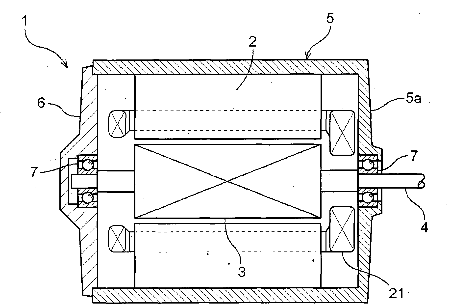
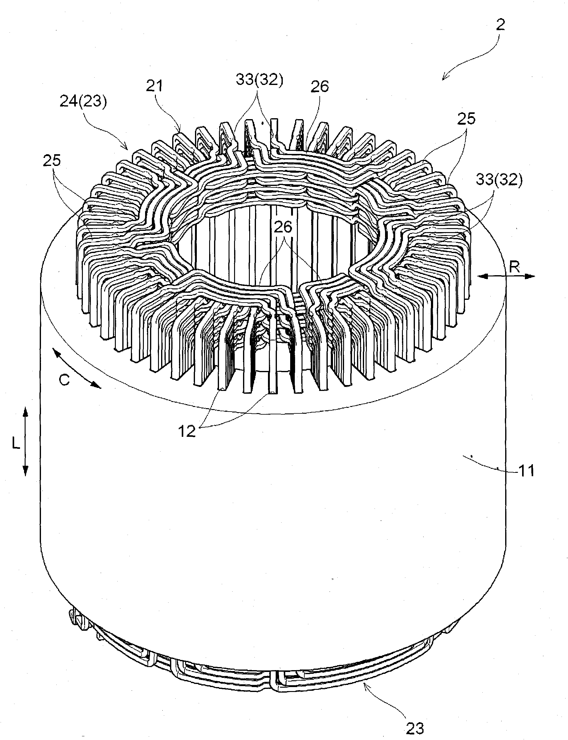
[0071] A first embodiment of an armature for a rotating electric machine according to the present invention will be described with reference to the drawings. In this embodiment, a case where the armature for a rotating electrical machine of the present invention is applied to the stator 2 of the rotating electrical machine 1 will be described as an example. figure 1 is a cross-sectional view showing the overall configuration of the rotating electric machine 1 according to the present embodiment, figure 2 It is a perspective view showing the overall structure of the stator 2 of this embodiment. The stator 2 of this embodiment is characterized by the combination of the stator core shape and the coil shape in order to improve the slot fill factor of the coil 21 in the slot 12 of the stator core 11 and reduce eddy current loss. Next, the configuration of each part of the rotary electric machine 1 will be described in detail.

[0072] 1-1. The overall configuration of the rotati...

no. 2 approach

[0114] Next, a second embodiment of the armature for a rotating electric machine according to the present invention will be described. Figure 13 It is a top view showing a part of the stator 2 of this embodiment. The stator core 11 included in the stator 2 has the same configuration as that of the above-mentioned first embodiment. However, in terms of the configuration of the coil 21 included in the stator 2 , specifically, the constricted concave portion 32 included in the coil 21 In terms of configuration, it is different from the first embodiment described above. Hereinafter, for the configuration of the armature for a rotating electrical machine according to the present embodiment, reference will be made as appropriate to Figure 13 to Figure 18 At the same time, the description will focus on the points of difference from the above-mentioned first embodiment. Moreover, it is the same as that of the said 1st Embodiment about the point which is not demonstrated especially...


PUM


Abstract

Provided is an armature for an electric rotating machine wherein the eddy current loss can be reduced while enhancing the space factor of coil. The present invention relates to an armature (2) for an electric rotating machine including a cylindrical core (11) where a plurality of slots (12) extending in the axial direction are positioned in a dispersion manner in the circumferential direction, and a coil (21) wound in the slots (12) each of which is formed in such a manner that the circumferential width of the inner circumferential opening of the slot (12) is narrower than the inner circumferential width of the slot, the circumferential width of a linear conductor constituting the coil is wider than the circumferential width of the inner circumferential opening, the coil end (23) of the coil (21) on one side in the axial direction thereof is a bent coil end (24); which is bent radially inward and provided with a radial conductor (25), and at a radial position in the radial conductor (25) corresponding to the inner circumferential opening, a narrow recess (32) which is recessed for other portion of the radial conductor (25) is provided so that the circumferential width becomes narrower than that of the inner circumferential opening.

Description

technical field [0001] The present invention relates to an armature for a rotating electric machine including a cylindrical iron core in which a plurality of axially extending slots are dispersedly arranged in the circumferential direction, and a coil wound in the slots, and a method for manufacturing the same. Background technique [0002] In general, in a rotating electric machine used as a motor, a generator, etc., it is required to be able to obtain a large output with a small body. Therefore, improving the energy efficiency of a rotating electric machine is one of the important subjects. Here, as a technique for improving the energy efficiency of a rotating electric machine, for example, a technique for increasing the slot fill factor of a coil in an armature of a rotating electric machine is conventionally known. [0003] The following patent document 1 is mentioned as a document which describes improvement of the slot fill factor of a coil. In the stator as an armat...

Claims


Application Information

Patent Timeline
Patent Type & Authority Applications(China)
IPC IPC(8): H02K15/06H02K3/04H02K3/34H02K15/10
CPCH02K3/12H02K15/067Y10T29/49009
Inventor 山本义久大竹新一篠原敬一古贺清隆
Owner AISIN AW CO LTD
Why Eureka
Try Eureka